EN - 3
1 IMPORTANT RECOMMENDATIONS
Your unit is equipped with a microprocessor-controlled electronic circuit board. To ensure the correct operation of your machine, you must follow
the rules listed below.
1.1 Electrical power supply
● Remote control: 230 V AC/50 Hz.
If the machine's remote control is powered separately (transformer
not supplied), provide the following:
1 - A power supply line running directly from a distribution point (this
line must be used only to supply power to the machine's remote
control).
2 - This power supply line must be at least 1 metre away from all
power lines (400 V).
1.2 Specifications of the XTRACONNECT 2 board
Board power input: 35 Watts.
Maximum allowable voltage and current per input/output:
253 V AC -3.15 A.
The board is powered by an onboard screw-on three-pin connector.
The terminals are identified as follows:
1 - Live,
2 - Neutral,
3 - Earth.
Board fuse specifications:
Schurter UMT 250 V AC/3.15 A. Time lag: 10 × 3. Product code:
34031 0171.
Environmental conditions:
- In storage: –40/+80°C, 5/85% humidity without condensation.
- In use: –20/+70°C, 5/85% humidity without condensation.
Degree of pollution: 3.
1.3 Warning
Read the instructions in the manual before attempting to service the
product.
Before attempting to service the board, disconnect its power source
and make sure that no voltage is present.
To prevent the risk of electric shock, access to the board should be
impossible while it is energised.
Certain parts of the board (USB and Ethernet connectors) may be
hot. Based on the ambient temperature, they could cause burns. As
a result, avoid touching these connectors while they are connected.
Important:
If the date and time are lost following a power failure, replace the
battery (type: Cr 2032).
There is a risk of explosion if the battery is replaced by an incorrect
type.
Dispose of used batteries in accordance with local regulations.
1.4 Earthing
The unit must be earthed (good earth quality in compliance with
French standard NF C 15-100).
1.5 Connection of sensors
Keep connection cables away from power lines (400 V) or a remote
control line (230 V). In the case of distances of over 6 m, use a
shielded cable connected to the earth on the unit.
Maximum distance: 25 m.
1.6 Connection of the communication buses and
of the remote console
● Connection cable specifications:
- Flexible cable for EIA – RS 485 connection
- Two shielded wires.
- Capacitance between cables and shield: 120 pF/m.
- Resistance: 56
Ω/km.
● Connection of the shield:
- Connect the shield on the BMS or micro-computer end to earth.
- Ensure bonding all the way to the last unit
(the shield on the communication cable must be connected
between each unit).
- Do not connect the shield to the earth connection on the units.
- The wires exiting the shield must be as short as possible (2 cm)
on each unit.
● Cable routing:
- The cable must be at least 30 cm away from all 230 V or 400 V
cables along its entire length.
- If a 230 V or 400 V cable must be crossed with a computer cable,
they must cross each other at a right angle.
1.7 Connection of the on/off inputs
● Distances of less than 30 metres:
- Use a shielded cable. Keep the cable at least 30 cm away from all
lines that could generate interference. Connect the shield to the
earth on the unit. If several shielded cables are used, connect each
shield separately (if the risk of interference persists, install a relay
for each input).
● Distances of greater than 30 metres:
- Install a relay for each input near the electronic circuit board
(cable cross-section: 0.5 mm2)
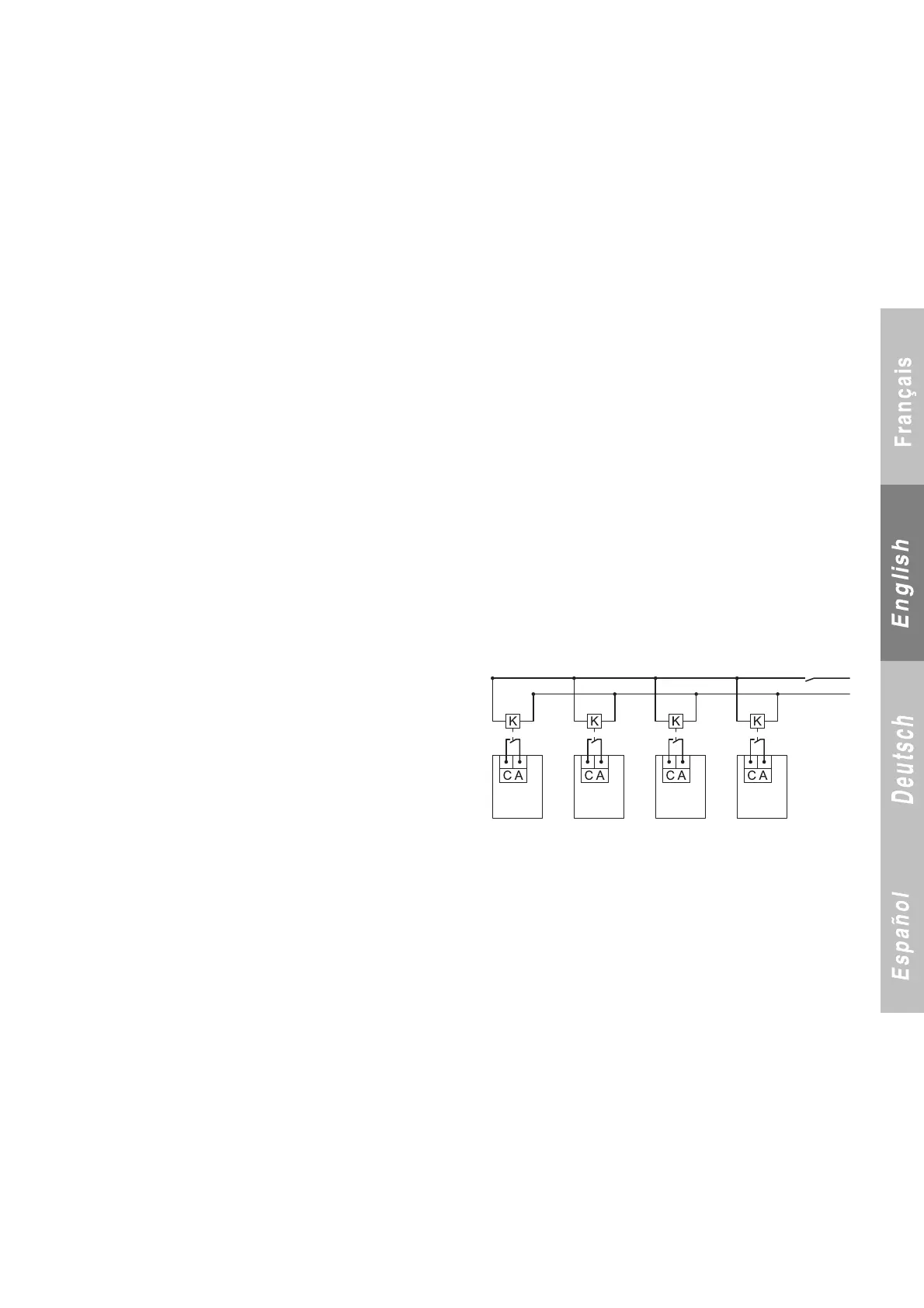
● Example connection diagram:
K: Auxiliary relay (fit near the electronic circuit board)
CA: Automatic operation control (on each machine)
2 GENERAL
This microprocessor-based electronic control module with display for liquid chillers is supplied as standard on water chillers equipped with screw
compressors with two or three refrigeration circuits.
Depending on the configuration, the board provides the following functions:
- Control of chilled water or hot water temperatures.
- Continuous monitoring of operating parameters.
- Diagnostics and fault storage.
- Setpoint drift based on the outdoor temperature (in heating and cooling modes).
- Communication with the console (remote or local) and the expansion boards (fault reporting, communication via modem for BMS and control
console).