EN - 8
J1
RC1
J6J5
J2
J4
J3
0
1
2
3
4
5
6
7
8
2 4 6 8 10 12 14 16
13579111315
54321321
54321
432 1432 1
TERMINAL BLOCK J5 (on/off inputs)
1: 230 V phase input common to the terminal outputs (24 V for
inverter compressor).
2: 230 V neutral input, common for redistribution on the terminal
block.
3: Neutral, compressor 3 protection.
4: Compressor 3 protection reset output (compressor 3 reset for
inverter 3).
5: Output to circuit 3 high-pressure switch (compressor 3 on/off, no
inverter faults).
6: Circuit 3 high-pressure switch feedback.
7: Compressor 3 winding 1 start output.
8: Available.
9: Compressor 3 winding 2 start output (compressor 3 start for
inverter).
TERMINAL BLOCK J6 (on/off outputs)
1: 230 V phase input common to the terminal outputs (24 V for
inverter compressor).
2: 230 V neutral input, common for redistribution on the terminal
block.
3: Available.
4: Available.
5: Available.
6: Available.
7: Available.
8: Available.
9: Available.
TERMINAL BLOCK J7
Serial port for Module 1 (3-circuit machine).
1: Terminal A.
2: Terminal B.
3: Shield.
TERMINAL BLOCK J8 (Molex)
Serial port for the expansion boards.
TERMINAL BLOCK J9 (on/off outputs)
1: Phase input common to terminals 2, 3 and 4.
2: Circuit 3 fan 1 output.
3: Circuit 3 fan 2 output.
4 :Circuit 3 fan 3 output.
5: Phase input common to terminals 6, 7 and 8.
6: Circuit 3 fan 4 output.
7: Circuit 3 fan 5 output.
8: Circuit 3 fan 6 output.
TERMINAL BLOCK J10 (on/off inputs)
1: Phase input common to terminals 2, 3 and 4.
2: Circuit 3 fault output.
3: Available.
4: Available.
5: Phase input common to terminals 6, 7 and 8.
6: Evaporator defrost heater output.
7: Desuperheater heater output.
8: Available.
TERMINAL BLOCK J11 (on/off inputs)
1: Phase input common to terminals 3, 5 and 6.
2: Neutral input common to the terminal outputs.
3: 25% valve output, compressor 3.
4: 25% valve and intake valve neutral.
5: Compressor 3 intake valve output.
6: Compressor 3 exhaust valve output.
7: Compressor 3 liquid valve and exhaust valve neutral.
8: Neutral input for terminal 12.
9: Phase input common to terminals 10-11.
10: Compressor 3 intake valve output.
11: Compressor 3 É
COCIAT valve output.
12: É
COCIAT valve neutral output.
TERMINAL BLOCK J12 (on/off outputs)
1: Phase input common to terminals 3, 5 and 6.
2: Neutral input common to the terminal outputs.
3: Available.
4: Available.
5: Available.
6: Available.
7: Available.
8: Neutral input for terminal 12.
9: Phase input common to terminals 10-11.
10: Available.
11: Available.
12: Available.
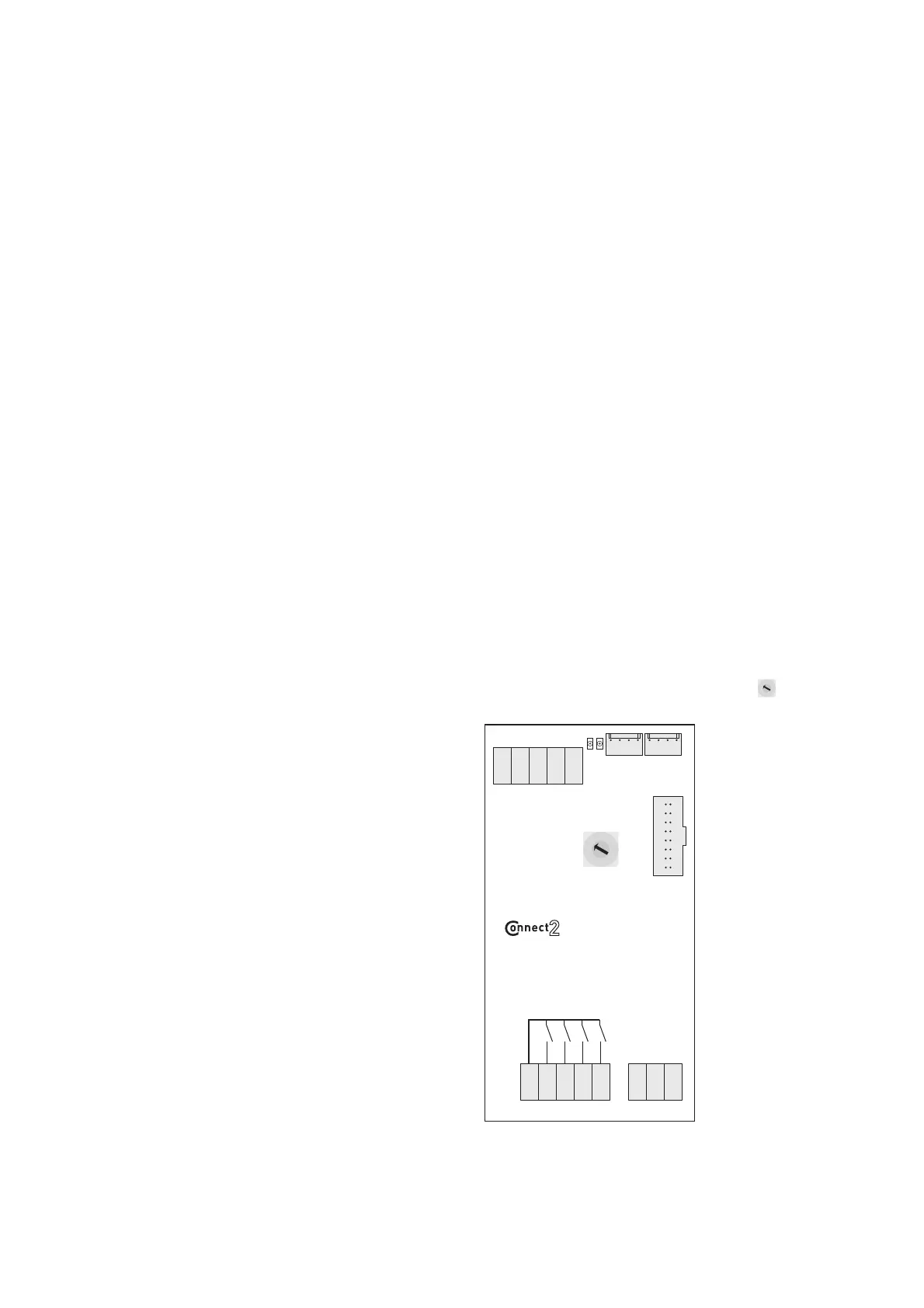
2.5 Description of expansion board 1 on a 3-circuit machine. Module 2, rotary switch set to '3'
0
1
2
3
4
5
6
7
8
TERMINAL BLOCK J1
Flash Memory connector.
TERMINAL BLOCK J2
Link with motherboard or another expansion board.
TERMINAL BLOCK J3
Link with another expansion board.
TERMINAL BLOCK J4 (on/off inputs)
1-2: Circuit 3 load shedding input.
2-3: Available.
4-5: Available.
TERMINAL BLOCK J5 (on/off inputs)
1: Common to all outputs: Compressor 3 intake valve
phase.
2 Available: Compressor 3 intake valve control.
3: Available.
4: Available.
5: Available.
TERMINAL BLOCK J6 (analogue inputs)
1-2: 10 K manifold water outlet temperature sensor,
3-circuit machine (2 modules).
2-3: Available.