EN - 7
RC1
0
1
2
3
4
5
6
7
8
J13
J7
13579111315
2 4 6 8 10 12 1416
123
J5
J8
J1
54321
1234
1234
45678123
9876
543219876
J12
9101112
J10
45678123
J9
45678123 45678123
J11
9101112
J4
543216
J6
543219876
11 10
J2
54321987611 10
J3
D15D14
K3
K1
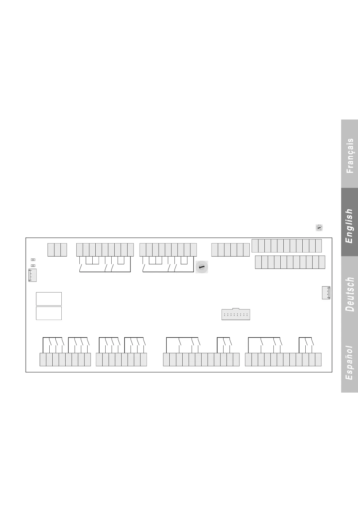
CIAT GAMME CONNECT2 ADD3
TERMINAL BLOCK J6 (on/off inputs)
1: 230 V phase input common to the terminal outputs (24 V for
inverter compressor).
2: 230 V neutral input, common for redistribution on the terminal
block.
3: Neutral, compressor 2 protection.
4: Compressor 2 protection reset output (compressor 2 reset for
inverter).
5: Output to circuit 2 high-pressure switch (compressor 2 on/off, no
inverter faults)
6: Circuit 2 high-pressure switch feedback.
7: Compressor 2 winding 1 start output.
8: Not used.
9: Compressor 2 winding 2 start output (compressor 2 start for
inverter).
TERMINAL BLOCK J7
Serial port for Module 2 (3-circuit machine).
1: Terminal A.
2: Terminal B.
3: Shield.
TERMINAL BLOCK J8 (Molex)
Serial port for the expansion boards.
TERMINAL BLOCK J9 (on/off outputs)
1: Phase input common to terminals 2, 3 and 4.
2: Circuit 1 fan 1 output.
3: Circuit 1 fan 2 output.
4: Circuit 1 fan 3 output.
5 Phase input common to terminals 6, 7 and 8.
6: Circuit 1 fan 4 output.
7: Circuit 1 fan 5 output.
8: Circuit 1 fan 6 output.
TERMINAL BLOCK J10 (on/off inputs)
1: Phase input common to terminals 2, 3 and 4.
2: Circuit 2 fan 1 output.
3: Circuit 2 fan 2 output.
4: Circuit 2 fan 3 output.
5 Phase input common to terminals 6, 7 and 8.
6: Circuit 2 fan 4 output.
7: Circuit 2 fan 5 output.
8: Circuit 2 fan 6 output.
TERMINAL BLOCK J11 (on/off outputs)
1 Phase input common to terminals 3-5-6.
2: Neutral input common to the terminal outputs.
3: 25% valve output, compressor 1.
4: 25% valve and intake valve neutral.
5: Compressor 1 intake valve output.
6: Compressor 1 exhaust valve output.
7: Compressor 1 liquid valve and exhaust valve neutral.
8: Neutral input for terminal 12.
9: Phase input common to terminals 10-11.
10: Compressor 1 intake valve output.
11: Compressor 1 É
COCIAT valve output.
12: É
COCIAT Valve neutral output.
TERMINAL BLOCK J12 (on/off outputs)
1 Phase input common to terminals 3-5-6.
2: Neutral input common to the terminal outputs.
3: 25% valve output, compressor 2.
4: 25% valve and intake valve neutral.
5: Compressor 2 intake valve output.
6: Compressor 2 exhaust valve output.
7: Compressor 2 liquid valve and exhaust valve neutral.
8: Neutral input for terminal 12.
9: Phase input common to terminals 10-11.
10: Compressor 2 intake valve output.
11: Compressor 2 É
COCIAT valve output.
12: É
COCIAT valve neutral output.
2.4 Description of expansion board 3 (ADD3) on a 3-circuit machine. Module 2, rotary switch set to '2'
2
TERMINAL BLOCK J1 (Molex)
Port available for expansion boards
TERMINAL BLOCK J2 (analogue inputs)
1: +5 V power supply for pressure sensor.
2: 0-5 V input for circuit 3 HP sensor.
3: 0-5 V input for circuit 3 LP sensor.
4: Common for pressure sensors.
5-6: Available.
7-8: 10 K circuit 3 suction temperature sensor.
8-9: 10 K circuit 3 liquid temperature sensor.
10-11: 50 K circuit 3 discharge temperature sensor.
TERMINAL BLOCK J3 (on/off inputs)
1-2: Water flow fault.
2-3: Circuit 3 manual reset HP fault (compressor 3 operation).
4-5: Compressor 3 protection fault (inverter compressor 3 fault)
6-8: Circuit 3 expansion valve fault.
7-8: Circuit 3 fan fault.
9-10: Phase controller fault.
10-11: 10 K circuit 3 exchanger water outlet temperature sensor
(2 modules).
TERMINAL BLOCK J4 (analogue outputs)
1-2: Pump 3 speed control (+ on terminal 1)
2-3: Circuit 3 fan speed control (+ on terminal 2)
4-5: Compressor 3 speed control (+ on terminal 4)
5-6: Not used.