Transmig 210, 250, 310, 330
Page 16 of 31 DOC No: MIGTRN0001
Date: 14/09/98 Issue No: 2
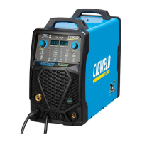
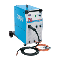
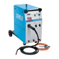
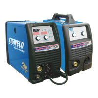
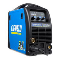
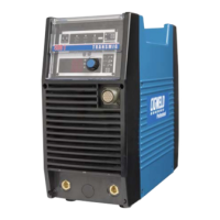
6. Power Source / 2R Wirefeeder Controls, Indicators and Features
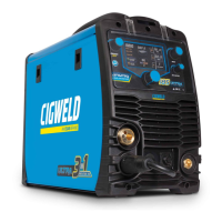
WirespeedControl
SpotTimerControl
DwellTimerControl
ModeSelector
Switch
BrassTorchAdaptor
IndicatorLight
On/Off&Coarse
VoltageControlSwitch
FineVoltage
ControlSwitch
NegativeWelding
CurrentTerminal
PositiveWelding
CurrentTerminal
OptionalMeter
(standardontheTransmig330)
TorchPolarityLead
IndicatorLight
On/Off&Coarse
VoltageControlSwitch
FineVoltage
ControlSwitch
NegativeWelding
CurrentTerminal
WirefeederControl
Socket
PositiveWelding
CurrentTerminal
OptionalMeter
(standardontheTransmig330)
Ammeter/Voltmeter
Switch
Figure 6 - Compact Transmig controls Figure 7 - Remote Transmig controls
6.1 Indicator Light
The indicator light is provided to indicate when the Transmig is connected to the Mains supply
voltage.
WARNING 3: When the light is lit, the machine is connected to the Mains supply voltage and
the internal electrical components are at Mains voltage potential.
6.2 Standby/Coarse Voltage Control Switch and Fine Voltage Control Switch
The Coarse Voltage Control switch turns off the fan and auxiliary power in the STANDBY position.
It sets the voltage level to the welding terminals in the remaining positions, increasing the voltage as
it is rotated in the clockwise direction. The Fine Voltage Control switch increases the voltage (in
smaller increments than the Coarse switch) as it is rotated in the clockwise direction.
WARNING 4: The Coarse & Fine Voltage Control switches MUST NOT BE SWITCHED
during the welding process.
Wirespeed
Control
SpotTimer
Control
PowerCable
ControlCable
GasHose
DwellTimer
Control
ModeSelector
Switch
BrassTorch
Adaptor
Figure 8 - Wirefeeder controls