Transmig 210, 250, 310, 330
DOC No: MIGTRN0001 Page 21 of 31
Issue No: 2 Date: 14/09/98
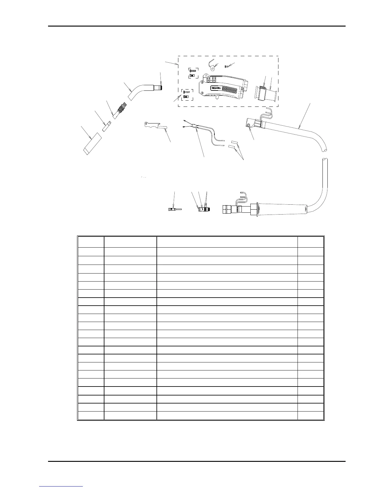
7.3 MIG Torch Components
Refer to Figure 10 for a pictorial representation of the components listed in Table 7.
1
2
3
4
5
6
7
22
23
8
14
9
13
12
10
11
18
17 1516
Figure 10 - Exploded view of MIG torch
Item Part No. Description Qty
1
¾
Nozzle (refer to Table 5)
1
2
¾
Contact tip (refer to Table 4)
1
3
¾
Gas diffuser (refer to Table 3)
1
4 WM6345 Conductor tube 1
5 OTW45B O-Ring, Gun Handle 1
6 OTW90721H Handle kit (includes items 7, 22 & 23) 1
7
Insert & screw (refer to item 6) 2
8 n/a Handle cap 1
9
n/a
Support 1
10 ELC94 Trigger Lever 1
11 ELC94B Trigger blades 1
12
¾
Butt Splice (insulated crimp link 1.5mm
2
) 2
13 ELC1042 Cap screw 1
14 OTW9072110 Cable assembly 1
15 OTW224 O-Ring, Connector Plug 2
16 OTW44C Set screw 8/32 UNC 1
17 OTW350174 Connector plug 1
18
¾
Conduit liner (refer to Table 6)
1
22
¾
Gun hanger (refer to item 6) 1
23
¾
Hanger screw (refer to item 6) 1
24 ELC94L Locking Trigger (not shown) (option)
Table 7 - MIG Torch components