Transmig 210, 250, 310, 330
DOC No: MIGTRN0001 Page 23 of 31
Issue No: 2 Date: 14/09/98
8. BASIC WELDING TECHNIQUE
8.1 Setting of the Power Source & Wirefeeder
The setting of the Transmig requires some practice by the operator, the welding plant having two
control settings that have to balance. These are the Wirespeed control and the welding Voltage
Control switches. The welding current is determined by the Wirespeed control, the current will
increase with increased Wirespeed, resulting in a shorter arc. Less wire speed will reduce the current
and lengthen the arc. Increasing the welding voltage hardly alters the current level, but lengthens the
arc. By decreasing the voltage, a shorter arc is obtained with a little change in current level.
When changing to a different electrode wire diameter, different control settings are required. A
thinner electrode wire needs more Wirespeed to achieve the same current level.
A satisfactory weld cannot be obtained if the Wirespeed and Voltage control switch settings are not
adjusted to suit the electrode wire diameter and the dimensions of the work piece.
If the Wirespeed is too high for the welding voltage, “stubbing” will occur as the wire dips into the
molten pool and does not melt. Welding in these conditions normally produces a poor weld due to
lack of fusion. If, however, the welding voltage is too high, large drops will form on the end of the
wire, causing spatter. The correct setting of voltage and Wirespeed can be seen in the shape of the
weld deposit and heard by a smooth regular arc sound.
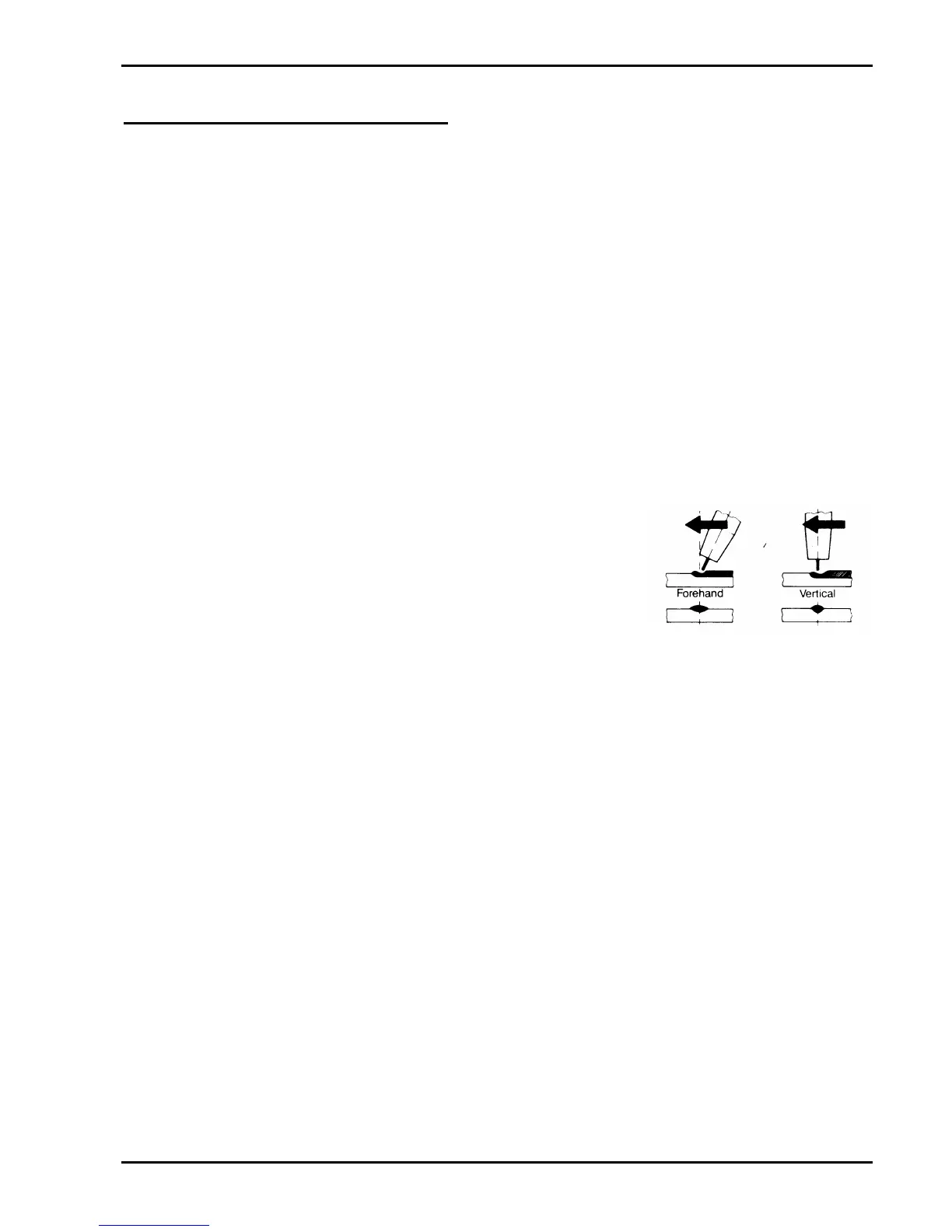
8.2 Position of MIG Torch
The angle of MIG torch to the weld has an effect on the width of
the weld run. Refer to Figure 12.
8.3 Distance from the MIG Torch Nozzle to the Work
Piece
The electrode wire stick out from the MIG Torch nozzle should
be between 2.0mm to 5.0mm. This distance may vary depending on the type of joint that is being
welded.
8.4 Travel Speed
Speed at which a weld travels influences the width of the weld and penetration of the welding run.
8.5 Stitch Welding Operation
Stitch welding is normally used to bridge excessive gaps between panels or when welding very thin
material to prevent heat build up and distortion. Set the controls as follows for stitch welding:
a) Coarse & Fine Voltage Control Switches and Wirespeed Control
Set these controls to obtain the desired welding conditions for the wire and material being
welded.
b) Mode Selector Switch
Set the MODE SELECTOR switch to STITCH.
c) Spot Time
Adjust the SPOT TIME control knob for the desired weld or 'ON' time whilst stitch welding.
d) Dwell Time
Adjust the DWELL TIME control knob for the desired interval or 'OFF' time whilst stitch
welding.
Figure 12 - MIG Torch angle