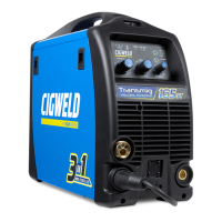
Transmig 210, 250, 310, 330
FIGURES
Page
Page 6 of 31 DOC No: MIGTRN0001
Date: 14/09/98 Issue No: 2
Figure 1 - Transmig duty cycle curves.....................................................................................................7
Figure 2 - Voltage settings for Transmig 210/250..................................................................................13
Figure 3 - Voltage settings for Transmig 310/330..................................................................................13
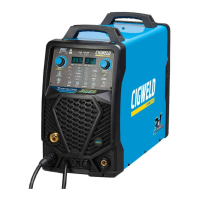
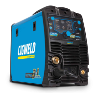
Figure 4 - Compact Transmig Setup......................................................................................................14
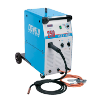
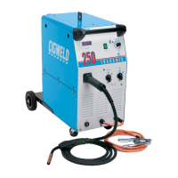
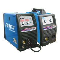
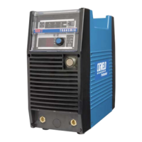
Figure 5 - Remote Transmig Setup........................................................................................................15
Figure 6 - Compact Transmig controls...................................................................................................16
Figure 7 - Remote Transmig controls.....................................................................................................16
Figure 8 - Wirefeeder controls...............................................................................................................16
Figure 9 - Examples of the digital read outs...........................................................................................17
Figure 10 - Exploded view of MIG torch...............................................................................................21
Figure 11 - Conduit liner trim length......................................................................................................22
Figure 12 - MIG Torch angle.................................................................................................................23