EL DC Instalation and operation manual v13.docx
24 / 56
In addition, CINERGIA units also integrate two terminals dedicated to an external Emergency
Power Off (EPO). When these terminals are used, the unit will have two Emergency Pushbuttons
active: the local pushbutton and the external-remote pushbutton. This document describes the
connection of the external-remote pushbutton (hereafter EPO).
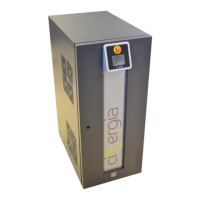
WARNING: the internal circuitry will be damaged if an external power supply is
connected to X12 (J15) EPO terminals. Do not connect an external power supply or
active signal. Only Normally Closed dry contact is allowed.
Figure 1: internal circuitry of EPO connection (J15 is X12 in above schematic)
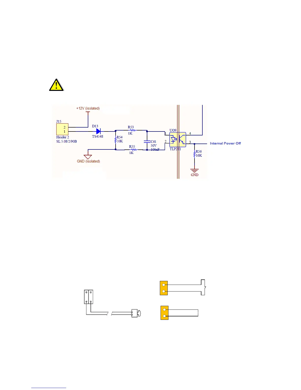
There are three alternatives for connection:
a) Connecting an external Emergency pushbutton to X12 (NC contact, without potential)
b) Installing a cable bridge/shunt to close the circuit in terminal X12 (in case an external
EPO is not used)
c) Using the X12 terminals to serialize an external Emergency Power Off sequence (Figure
3)
The figures below describe the connection of the EPO.