EL DC Instalation and operation manual v13.docx
9 / 56
2.3. Operation and connection modes
The output of the power converter is formed by three phases referenced to the neutral point of
the system (N). Consequently, the user can choose between two possible connection modes for
the electronic load:
- Independent phases: each phase (U, V, W) is controlled independently. The current
setpoint can be different in angle and magnitude for each of the three phases.
- Parallel phases: It is exactly the same as the previous case, but in this case the user has
shorted the phases. In this case the total amount of current consumed will be the sum
of all three phases.
- Unipolar mode: Electronic Load behaves as 3 independent and positive DC power
supplies.
- Bipolar mode: Electronic Load behaves as 2 independent DC power supplies. One is
positive and the other negative.
Three operation modes are allowed:
- Constant Impedance (CI): the output impedance is controlled to the set point value. The
emulator will perform as a constant R.
- Constant Current (CC): the output current is controlled to the set point value.
- Constant Power (CP): the output active power is regulated to the set point value.
- Constant Voltage (CV): the output voltage is controlled to the set point value.
2.4. Configuration and control of the converter
The converter can be interfaced by three means:
- Local touchscreen: a 3.2” color local touchscreen panel can be used to configure,
monitor and operate the electronic load. See section Local Touchscreen Control Panel
for further information.
- Analog and digital inputs: the converter owns three isolated analog inputs (+/-10V) and
tow optocoupled digital inputs.
- Remote interface: an Ethernet communication interface with protocol MODBUS/TCP
can be used to configure, monitor and operate the electronic load. By using HMI
software application provided by CINERGIA, uploading of excel files is also possible.
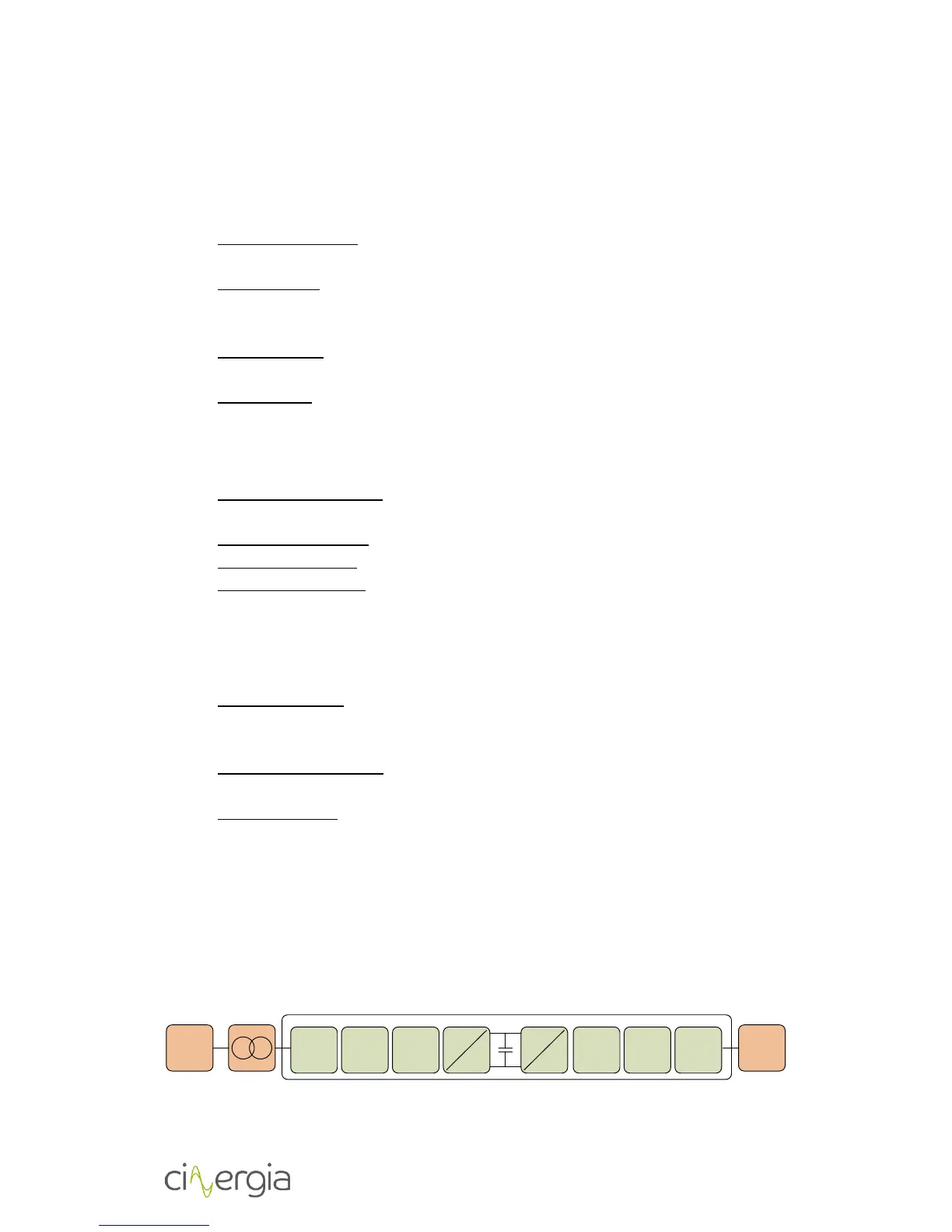
2.5. Functional diagram
The diagram below is the conceptual function block diagram of the converter: