EL DC Instalation and operation manual v13.docx
27 / 56
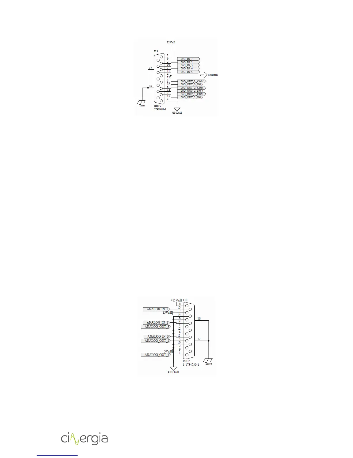
The list of each digital functionality is the following (Note that those are default
functionalities). (The maximum admitted input voltage is 10V and 12 output voltage)
- DIG_IN_1: Enable console mode
- DIG_IN_2: Run equipment
- DIG_IN_3: Emergency stop
- DIG_IN_4: Rearme (used in combination: Rearme+Stop=Reset / Rearme+Run=Enable)
- DIG_IN_5: Single push: Ready. Long push: disable
Relay normally open output contact (3A, 250VAC / 3A, 30VDC)
- DIG_OUT_1_NO: Run (signal in run, ready and initialization)
- DIG_OUT_2_NO: Alarm (signal in alarm and initialization)
- DIG_OUT_3_NO: Ready (signal in ready, initialization and blinking during precharge)
In standby, none of the digital output is activated.
3.4.8. Analog inputs and outputs (AIO Optional)
Analog inputs and outputs are gathered in X17.
The analog input of EL is isolated and accept a voltage range from ‐10 to 10V. There is only one
analog input and it corresponds to the current setpoint for all three phases. If the analog input
is set to zero volts, that corresponds to 0A. In this way, by setting 10V, the EL will supply or sink
(depending on the sign) the rated current specified in the datasheet.