DA-1000 User’s Manual
78
5.1 Digital I/O (DIO) application
This section describes DIO application of the product. The content and
application development are better understood and implemented by well
experienced professionals or developers.
Chapter 5: Product application
5.1.1 Digital I/O Programming Guide
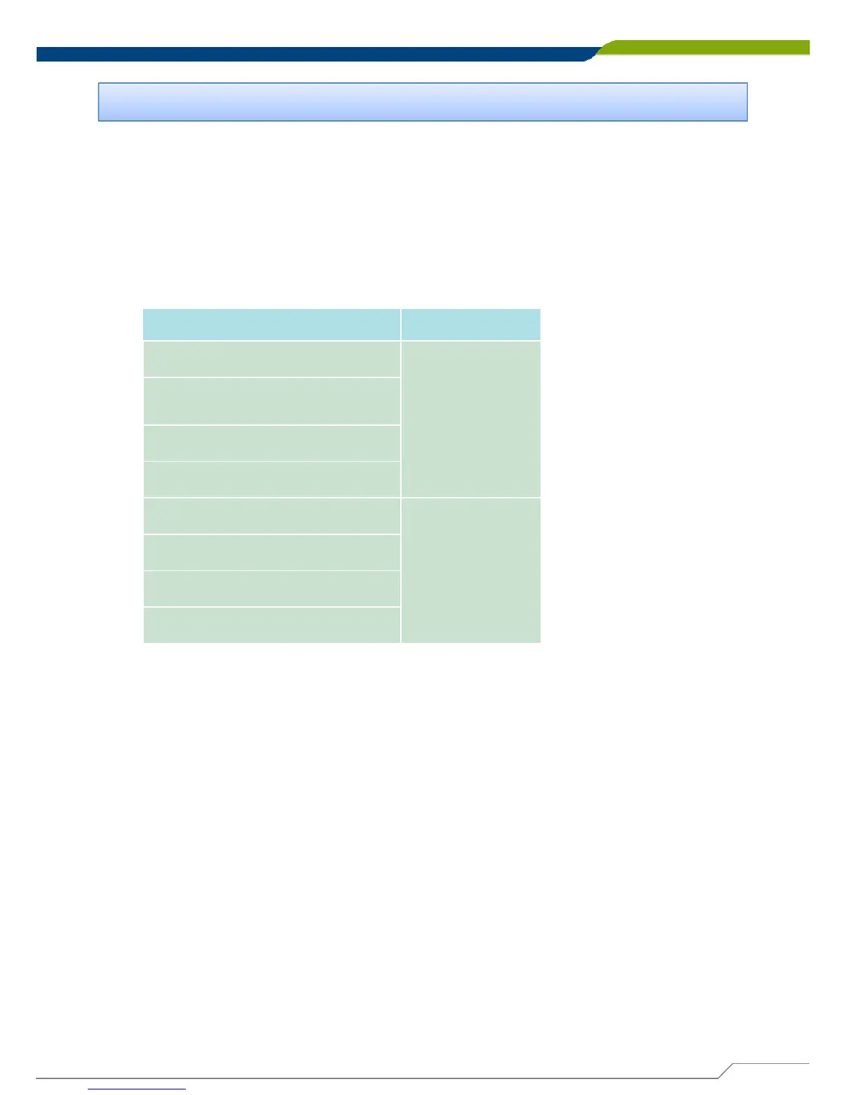
5.1.1.1 Pins for Digital I/O for Cincoze DA series product
Item Standard
GPIO54 (Pin13)
DI
GPIO55 (Pin14)
GPIO56 (Pin15)
GPIO57 (Pin16)
GPIO60 (Pin17)
DO
GPIO61 (Pin18)
GPIO62 (Pin19)
GPIO63 (Pin20)
5.1.1.2 Programming Guide
To program the Super I/O chip F81866A configuration registers, the following
configuration procedures must be followed in sequence:
(1) Enter the Extended Function Mode
(2) Configure the configuration registers
(3) Exit the Extended Function Mode
The configuration register is used to control the behavior of the corresponding
devices. To configure the register, use the index port to select the index and then
write data port to alter the parameters. The default index port and data port are 0x4E
and 0x4F respectively. Pull down the SOUT1 pin to change the default value to
0x2E/ 0x2F. To enable configuration, the entry key 0x87 must be written to the
index port. To disable configuration, write exit entry key 0xAA to the index
port. Following is an example to enable configuration and to disable configuration by
using debug.
-o 4e 87
-o 4e 87 (enable configuration)
-o 4e aa (disable configuration)
This chapter descripts the DIO applications.