DA-1000 User’s Manual
82
Chapter 5: Product application
5.1.1.5 Change base address
<Enter the Extended Function Mode>
WriteByte(AddrPort, 0x87)
WriteByte(AddrPort, 0x87) // Must write twice to enter Extended mode
<Select Logic Device>
WriteByte(AddrPort, 0x07)
WriteByte(dataPort, 0x06)
// Select logic device 06h
WriteByte(AddrPort, 0x60) // Select configuration register 60h
WriteByte(DataPort, (ReadByte(DataPort) ǀ 0x03))
WriteByte(AddrPort, 0x61) // Select configuration register 61h
WriteByte(DataPort, (ReadByte(DataPort) ǀ 0x20))
<Leave the Extended Function Mode>
WriteByte(AddrPort, 0xAA)
GPIO Port base address 0x0320/h
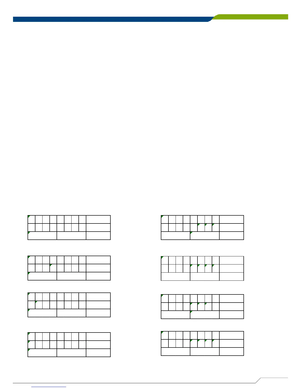
5.1.1.6 DATA Bit Table (DIO)
= DI1
76543210 bit
0001---- value
/h
1X
= DI2
76543210 bit
0010---- value
/h
2X
= DI3
76543210 bit
0100---- value
/h
4X
= DI4
76543210 bit
1000---- value
/h
8X
= DO1
76543210 bit
----0001 value
/hX
1
= DO2
76543210 bit
----0010 value
/hX2
= DO3
76543210 bit
----0100 value
/hX
4
= DO4
76543210 bit
----1000 value
/hX8