CISCO CONFIDENTIAL - First Draft
1-3
Cisco Aironet 1300 Series Bridge Hardware Installation Guide
OL-5048-01
Chapter 1 Overview
Key Features
Power
The bridge receives inline power from the Cisco Aironet Power Injector (hereafter called the power
injector). Dual-coax cables are used to provide Ethernet data and power from the power injector to the
bridge. The power injector is an external unit designed for operation in a sheltered environment, such as
inside a building or vehicle. The power injector also functions as an Ethernet repeater by connecting to a
Category 5 LAN backbone and using the dual-coax cable interface to the bridge.
The power injector uses an external 48-VDC power module and injects the DC voltage into the dual-coax
cables to power the bridge. The power injector can be also directly connected to a +12 VDC to +48 VDC
power source, such as a vehicle battery.
Note The power injector and the power module should not be placed in an outdoor unprotected environment or
in an environmental air space, such as above a suspended ceiling.
Integrated Antenna
The bridge is available with an integrated 13-dBi patch array antenna. The antenna is covered with a
radome to protect it from environmental elements. When configured with the integrated antenna, the
antenna polarization is controlled by the mounting orientation of the bridge.
Note Some international regulatory regions may restrict the integrated antenna bridge configuration.
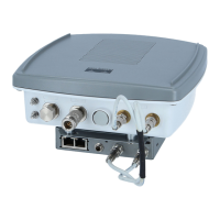
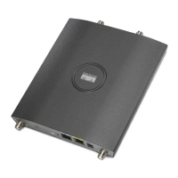
External Antenna
The bridge is available in an external antenna configuration (see Figure 1-1) for use with existing Cisco
Aironet 2.4-GHz antennas. Two reverse-TNC type RF connectors are provided on the end of the unit to
support single or diversity antenna configurations.
The antennas connect to the bridge antenna connectors using a coax cable. The list below contains some
of the external antennas supported by the bridge.
• 2.2 dBi omnidirectional
• 5.2-dBi omnidirectional antenna with vertical polarization
• 12-dBi omnidirectional antenna with vertical polarization
• 9-dBi patch wall mount antenna
• 10 dBi yagi antenna
• 13.5 dBi yagi antenna
• 15-dBi sector antenna with vertical polarization
• 21-dBi dish antenna
Note To meet regulatory restrictions, the external antenna BR1300 configuration and the external antenna
must be professionally installed. The network administration or other IT professional responsible for
installing and configuring the unit is a suitable professional installer. Following installation, access to the
unit should be password protected by the network administrator to maintain regulatory compliance.
 Loading...