CISCO CONFIDENTIAL - First Draft
8-5
Cisco Aironet 1300 Series Bridge Hardware Installation Guide
OL-5048-01
Chapter 8 Troubleshooting
Checking Power
Checking Power
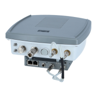
You can verify the availability of power to the bridge by checking the power injector LED (see
Figure 8-2):
• Power LED
–
Green color indicates 48 VDC is available (see Figure 8-2).
–
Off indicates 48 VDC is not available—verify that the power module is connected to the power
injector and to an AC receptacle and that AC power is available.
Checking Basic Configuration Settings
Mismatched basic settings are the most common causes of lost wireless connectivity. If the bridge does
not associate with a remote bridge, check the following areas.
SSID
To associate, all bridges must use the same SSID. The bridge installation mode SSID is autoinstall and
the normal mode default SSID is tsunami. You should verify that the SSID value shown on the Express
Setup page is the same for all bridges. You should also verify that the bridges are configured for the
proper network role; only one bridge can be configured as the root bridge.
Security Settings
Remote bridges attempting to authenticate to your bridge must support the same security options
configured in the bridge, such as WEP, EAP or LEAP, MAC address authentication, Message Integrity
Check (MIC), WEP key hashing, and 802.1X protocol versions.
If a non-root bridge is unable to authenticate to your root bridge, verify that the security settings are the
same as your bridge settings. For additional information, refer to the Cisco IOS Software Configuration
Guide for Cisco Aironet Bridges.
Antenna Alignment
If your non-root bridges are unable to associate to your root bridge, you should verify the basic
configuration settings on all bridges before attempting to verify bridge antenna alignment (refer to
“Configuring the Bridge for the First Time” section on page 5-1). If your basic configuration settings are
correct, you can verify antenna alignment by using the Install mode RSSI LED indications. For
additional information, refer to the “Aligning the Antenna Using RSSI LED Indications” section on
page 3-5.
1 Dual-Coax Ethernet Ports 4 RJ-45 Ethernet Connector
2 Power LED 5 RJ-45 Serial Console Port
3 Power Jack (12 to 48 VDC)
 Loading...