EasyManuals Logo

Cisco Catalyst 3560-CX User Manual

Cisco Catalyst 3560-CX
88 pages
To Next Page IconTo Next Page
To Previous Page IconTo Previous Page
Page #33 background imageLoading...
Page #33 background image
Step 7
Remove the screw template from the wall.
Step 8
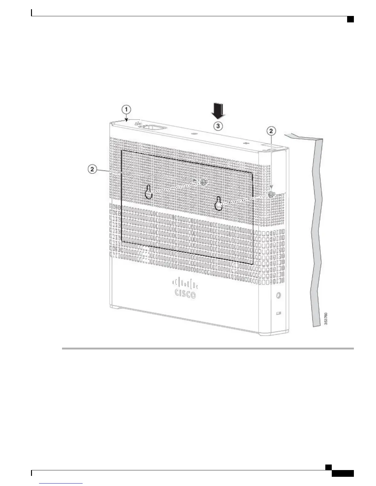
Place the switch onto the mounting screws, and slide it down until it locks in place.
Figure 14: Installing the Switch on a Wall
With a Mounting Tray
The mounting kit (part number CMPCT-MGNT-TRAY=) is optional. You can order it when you order your
switch, or you can order it later from your Cisco representative.
The mounting kit ships contents:
Two number-10 Phillips pan-head screws
Catalyst 3560-CX and 2960-CX Switch Hardware Installation Guide
23
Switch Installation
With a Mounting Tray

Table of Contents

Other manuals for Cisco Catalyst 3560-CX

Questions and Answers:

Question and Answer IconNeed help?

Do you have a question about the Cisco Catalyst 3560-CX and is the answer not in the manual?

Cisco Catalyst 3560-CX Specifications

General IconGeneral
ModelWS-C3560CX-8PC-S
Switching Capacity20 Gbps
Product TypeSwitch
ManageableYes
Layer SupportedLayer 3
Jumbo Frame SupportYes
Jumbo Frame Size9198 bytes
Input Voltage100 - 240 VAC
Operating Temperature32 to 113°F (0 to 45°C)
Power SupplyInternal
Ports8 x 10/100/1000 Ethernet Ports
Uplink Ports2 x 1G SFP
PoEPoE+
Form FactorDesktop, Wall-mountable
MAC Address Table Size16, 000 entries
Power SourceAC

Related product manuals