15-27
Catalyst 6500 Series Switch and Cisco 7600 Series Router Firewall Services Module Configuration Guide
OL-6392-01
Chapter 15 Using Failover
Failover Configuration Example
Failover Configuration Example
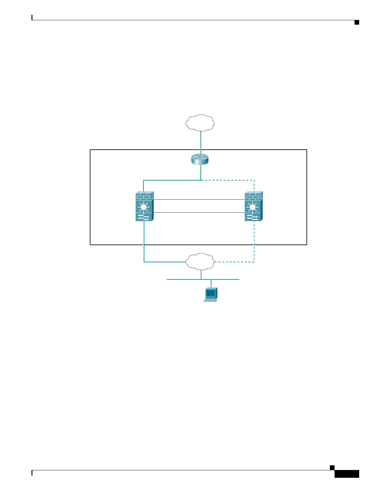
Figure 15-8 shows the network diagram for a failover configuration within a switch. The only difference
between the configuration of inter-switch and intra-switch failover is on the switch; the configuration
on the FWSM is the same.
Figure 15-8 Failover Scenario
Active FWSM
209.165.201.1
PAT: 209.165.201.5
VLAN 200
Switch
VLAN 100
VLAN 201
Standby FWSM
209.165.201.2
Internet
State VLAN 11
Failover VLAN 10
Inside
Web Server 192.168.2.5
Static: 209.165.201.5
192.168.2.1 192.168.2.2
192.168.253.5
192.168.253.1
192.168.253.6
192.168.253.2
104649
 Loading...


