B-2
Catalyst 6500 Series Switch and Cisco 7600 Series Router Firewall Services Module Configuration Guide
OL-6392-01
Appendix B Sample Configurations
Routed Mode Examples
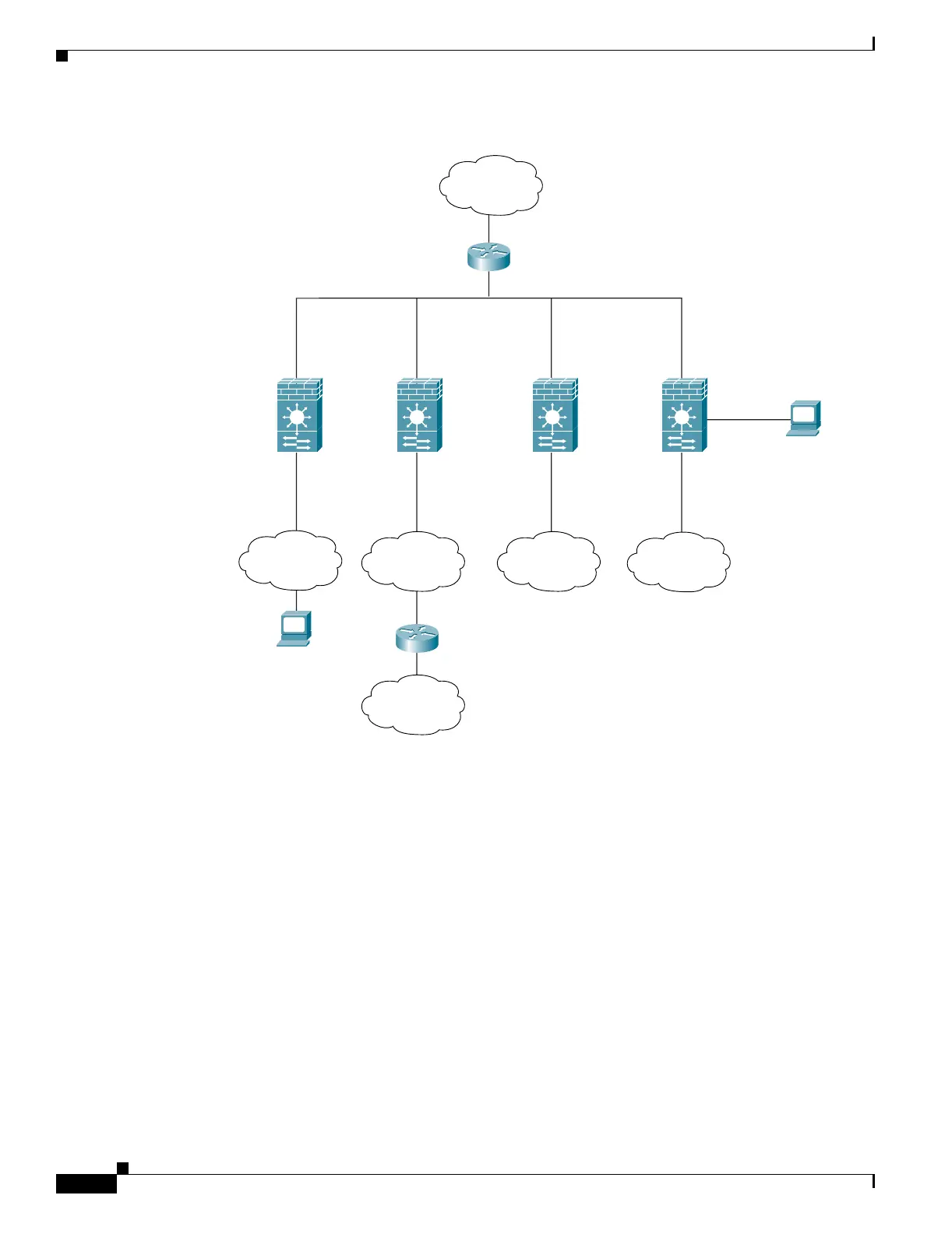
Figure B-1 Example 1
See the following sections for the configurations for this scenario:
• Example 1: System Configuration, page B-2
• Example 1: Admin Context Configuration, page B-3
• Example 1: Customer A Context Configuration, page B-4
• Example 1: Customer B Context Configuration, page B-4
• Example 1: Customer C Context Configuration, page B-4
• Example 1: Switch Configuration, page B-5
Example 1: System Configuration
You must first enable multiple context mode using the mode multiple command. Then enter the
activation key to allow more than two contexts using the activation-key command. The mode and the
activation key are not stored in the configuration file, even though they do endure reboots. If you view
the configuration on the FWSM using the write terminal, show startup, or show running commands,
the mode displays after the FWSM Version (blank means single mode, “<system>” means you are in
multiple mode in the system configuration, and <context> means you are in multiple mode in a context).
customerA
outside
209.165.201.3
customerB
outside
209.165.201.4
customerC
outside
209.165.201.5
VLAN 7
VLAN 8
VLAN 6VLAN 5
VLAN 3
MSFC
209.165.201.1
Internet
Admin
Network
customerA
Network 1
customerA
Network 2
customerB
Network
customerC
Network
Admin Context
outside
209.165.201.2
inside
10.1.2.1
10.1.2.2
192.168.1.1
Management host
10.1.1.75
inside
10.1.3.1
inside
10.1.4.1
DMZ
192.168.2.1
inside
10.1.1.1
VLAN 4
Websense
192.168.2.2
104645