B-19
Catalyst 6500 Series Switch and Cisco 7600 Series Router Firewall Services Module Configuration Guide
OL-6392-01
Appendix B Sample Configurations
Transparent Mode Examples
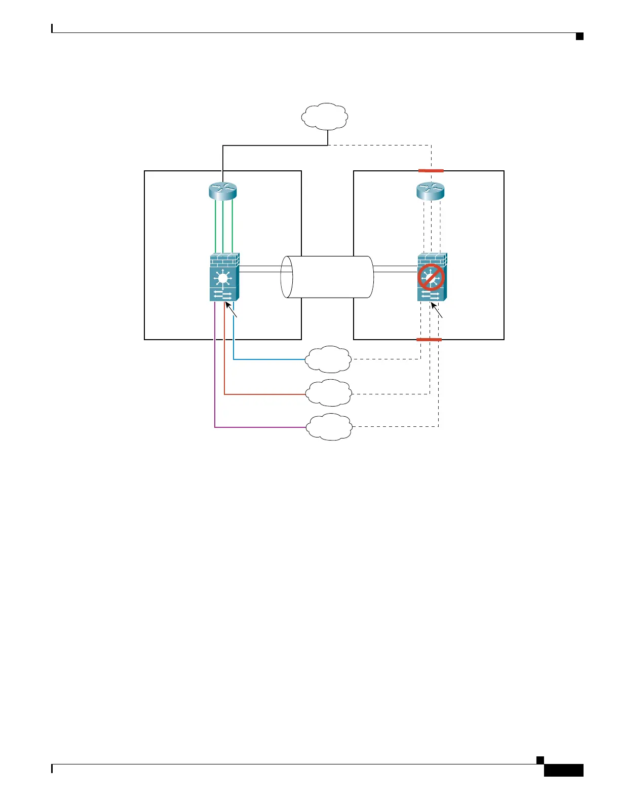
Figure B-6 Example 6
See the following sections for the configurations for this scenario:
• Example 6: Primary FWSM Configuration, page B-19
• Example 6: Secondary FWSM System Configuration, page B-21
• Example 6: Switch Configuration, page B-21
Example 6: Primary FWSM Configuration
The following sections include the configuration for the primary FWSM:
• Example 6: System Configuration (Primary), page B-19
• Example 6: Context A Configuration (Primary), page B-20
• Example 6: Context B Configuration (Primary), page B-20
• Example 6: Context C Configuration (Primary), page B-21
Example 6: System Configuration (Primary)
You must first enable multiple context mode using the mode multiple command. Then enter the
activation key to allow more than two contexts using the activation-key command. The mode and the
activation key are not stored in the configuration file, even though they do endure reboots. If you view
Primary
FWSM
VLANs 200-202
MSFC
HSRP IPs:
10.0.
n
.4
MSFC
HSRP IPs:
10.0.
n
.4
10.0.3.1
Mgmt IPs:
10.0.1.1
10.0.2.1
VLAN 100
VLAN 6
Context A
Context B
Context C
Active Switch
Secondary
FWSM
Standby Switch
Trunk:
VLANs 200, 201,
202, 4, 5, 6, 10, 11
Internet
VLAN 5
VLAN 11
VLAN 10
Failover Links:
VLAN 4
10.0.3.2
Mgmt IPs:
10.0.1.2
10.0.2.2
115000