B-12
Catalyst 6500 Series Switch and Cisco 7600 Series Router Firewall Services Module Configuration Guide
OL-6392-01
Appendix B Sample Configurations
Routed Mode Examples
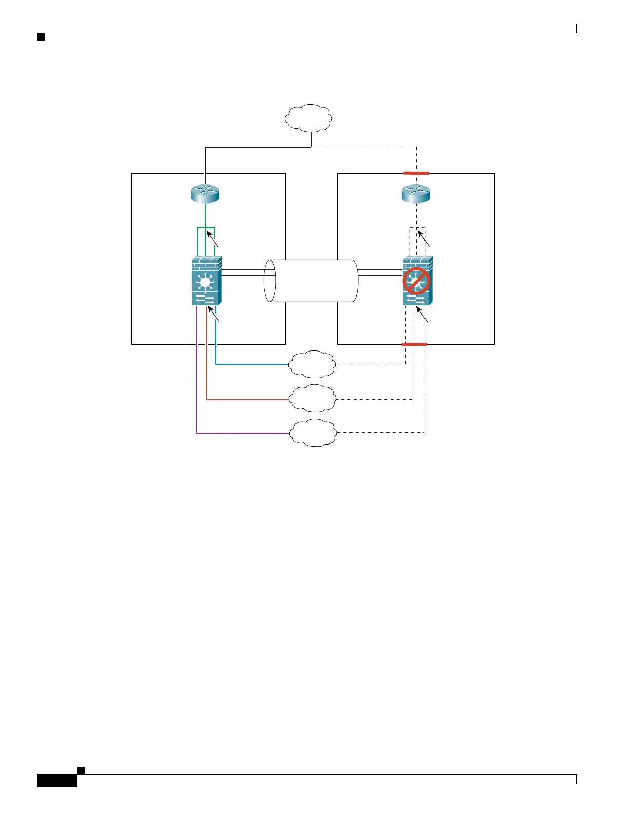
Figure B-4 Example 4
See the following sections for the configurations for this scenario:
• Example 4: Primary FWSM Configuration, page B-12
• Example 4: Secondary FWSM System Configuration, page B-14
• Example 4: Switch Configuration, page B-14
Example 4: Primary FWSM Configuration
The following sections include the configuration for the primary FWSM:
• Example 4: System Configuration (Primary), page B-12
• Example 4: Context A Configuration (Primary), page B-13
• Example 4: Context B Configuration (Primary), page B-13
• Example 4: Context C Configuration (Primary), page B-14
Example 4: System Configuration (Primary)
You must first enable multiple context mode using the mode multiple command. Then enter the
activation key to allow more than two contexts using the activation-key command. The mode and the
activation key are not stored in the configuration file, even though they do endure reboots. If you view
Primary
FWSM
VLAN 200
MSFC
HSRP IP:
209.165.201.5
MSFC
HSRP IP:
209.165.201.5
209.165.201.2
209.165.201.6
209.165.201.3
209.165.201.7
10.0.3.110.0.1.1
10.0.2.1
VLAN 100
VLAN 203
Context A
Context B
Context C
Active Switch
Secondary
FWSM
Standby Switch
Trunk:
VLANs 200, 201,
202, 203, 10, 11
Internet
VLAN 202
VLAN 11
VLAN 10
Failover Links:
VLAN 201
209.165.201.4
209.165.201.8
10.0.3.210.0.1.2
10.0.2.2
104893