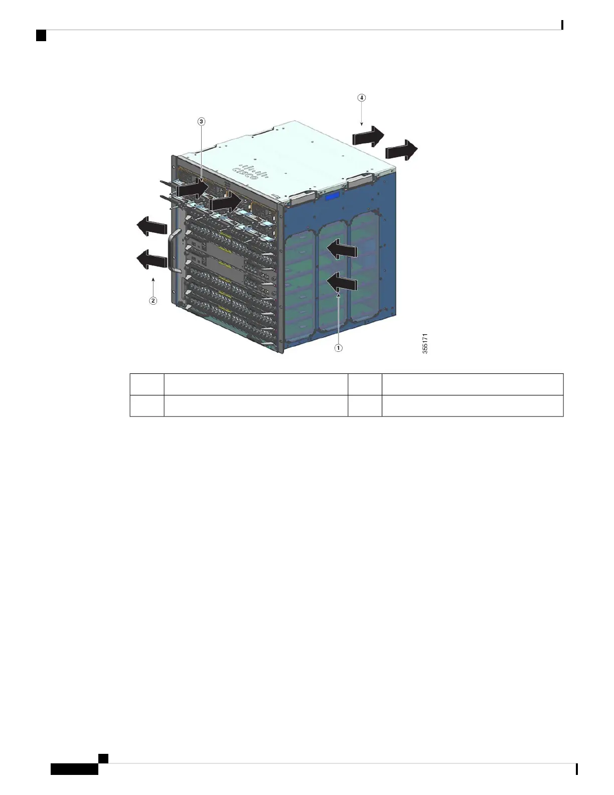
Power supply air intake3Chassis air intake1
Power supply air exhaust4Chassis air exhaust2
If you are installing your switch in an enclosed or partially enclosed rack, we strongly recommend that you
verify that your site meets the following guidelines:
• Verify that there is a minimum of 6 inches (15 cm) of clearance between the sides, front, and back of
any enclosure, and both the chassis air intake grill and the chassis air exhaust grill along with the power
supply unit intakes and exhausts. The upright columns of a relay rack may be located less than the
recommended side spacing provided there are substantial cutouts, holes, or vents in the structure to allow
adequate air flow through the chassis.
• Verify that the ambient air temperature within the enclosed or partially enclosed rack is within the chassis
operating temperature limits. After installing the chassis in the rack, power up the chassis and allow the
chassis temperature to stabilize (approximately 2 hours).
Measure the ambient air temperature at the chassis air intake grill by positioning an external temperature
probe 1 inch (2.5 cm) away from the chassis left side, and centered on the chassis both horizontally and
vertically.
Measure the ambient air temperature at the power supply unit air intake grill by positioning an external
temperature probe 1 inch (2.5 cm) away from the chassis front, centered on the power supply unit section
located above the card slots.
• If the ambient intake air temperature is less than 109°F (45°C) at altitudes of 6,000 feet and below,
the rack meets the intake air temperature criterion. At altitudes above that threshold and up to 10,000
feet (3000 m), the air intake should not exceed 104°F (40°C).
Cisco Catalyst 9400 Series Switches Hardware Installation Guide
28
Preparing for Installation
Air Flow