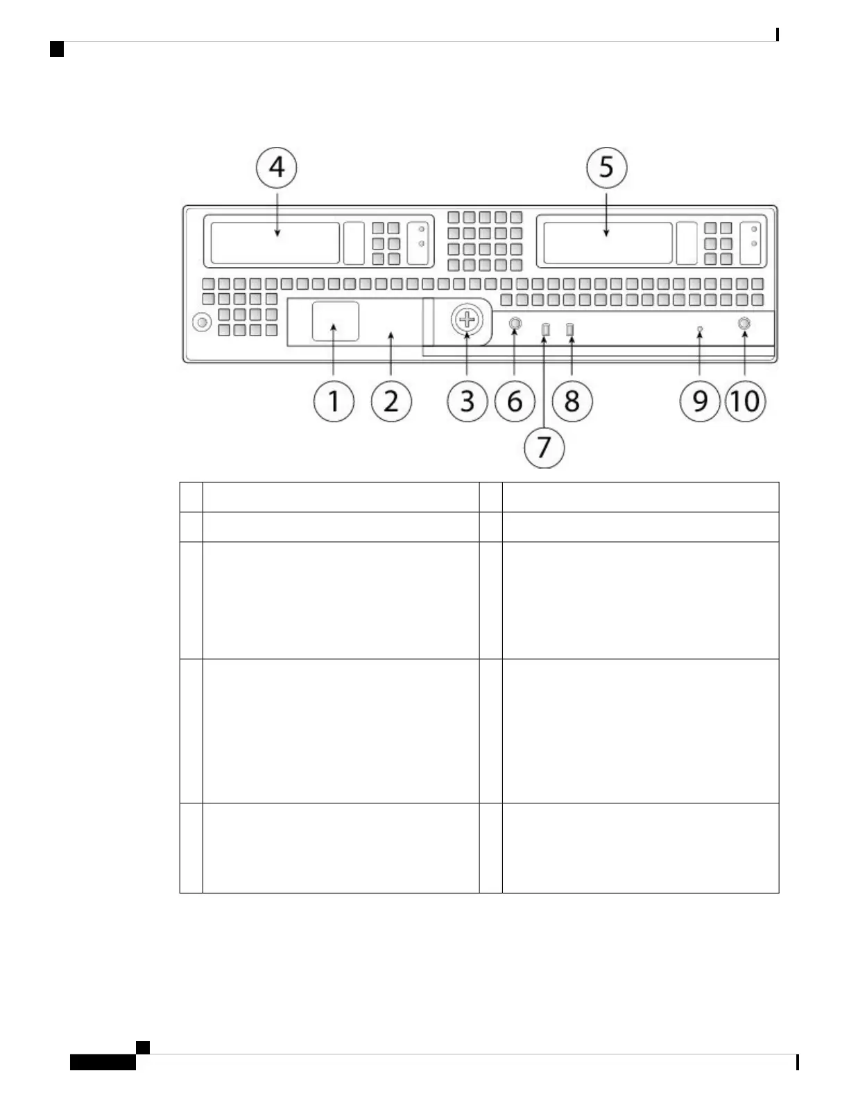
Figure 8: Firepower 9300 Security Module Front Panel
Security module ejector handle2Paper tab for server name or serial number1
SSD bay 14Ejector handle captive screw3
Power button and LED
• Off—No power.
• Green—System has power.
• Amber—Standby power.
6SSD bay 25
Security module health LED
• Off—Power off.
• Green—Normal operation.
• Amber—Minor error.
• Amber, flashing—Critical error.
8Network link status LED
• Off—No network connection.
• Green—At least one network is up.
• Green, flashing—Network activity faster
than 1 G.
7
Locator/Beacon (push button) and LED
• Off—Locate is off.
• Blue—Locate is on.
10Reset button access9
There are six supported security modules:
• SM-24—24-physical core CPU security module (NEBS ready)
• SM-36—36-physical core CPU high performance security module
Cisco Firepower 9300 Hardware Installation Guide
14
Overview
Security Modules

 Loading...