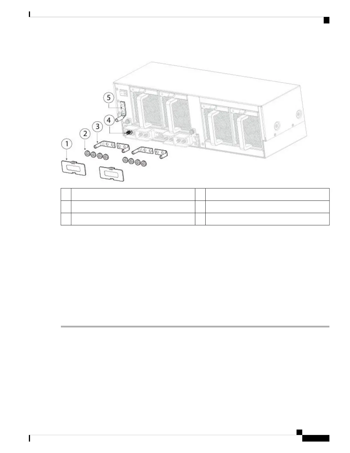
Figure 48: Connect the DC Power Connectors and Ground Lugs
Nuts2DC terminal covers1
DC terminals4Two 2-hole lugs (not provided in accessory kit)3
Chassis ground lug5
Step 7 Connect the DC-input wires to the power entry module terminal block. The proper wiring sequence is positive to positive
(red wire) and negative to negative (black wire).
Step 8 Replace the terminal covers as shown in the figure above.
This cover should always be in place when power is applied to the terminals.
Step 9 Set the DC disconnect switch in the circuit to ON.
In a system with multiple power supplies, connect each power supply to a separate DC power source. In the
event of a power source failure, if the second source is still available, it can maintain system operation.
Caution
Step 10 Verify power supply operation by checking the power supply LED on the front of the chassis.
See Power Supply Modules, on page 26 for the LED values.
Connect the HVDC Power Supply Module
Take note of the following warnings:
Cisco Firepower 9300 Hardware Installation Guide
73
Installation, Maintenance, and Upgrade
Connect the HVDC Power Supply Module

 Loading...