Figure 29: Stripping the Input Power Source Wire
Step 5 Insert the wire into a spade terminal, and crimp it to the wire.
You can also use a ring or flanged spade terminal. See Equipment That You Need, on page 40.
Figure 30: Crimping the Spade Terminal Lug
Step 6 Loosen the terminal screw, and slide the terminal under the screw and washer.
Use the appropriate terminal screws based on power supply type: high-voltage (AC or DC) or low-voltage
(DC).
Note
Step 7 Make the power connection:
a) AC Power Connection
Connect the line wire into the terminal screw labeled L and the neutral wire into the terminal screw labeled N to
complete the AC connection.
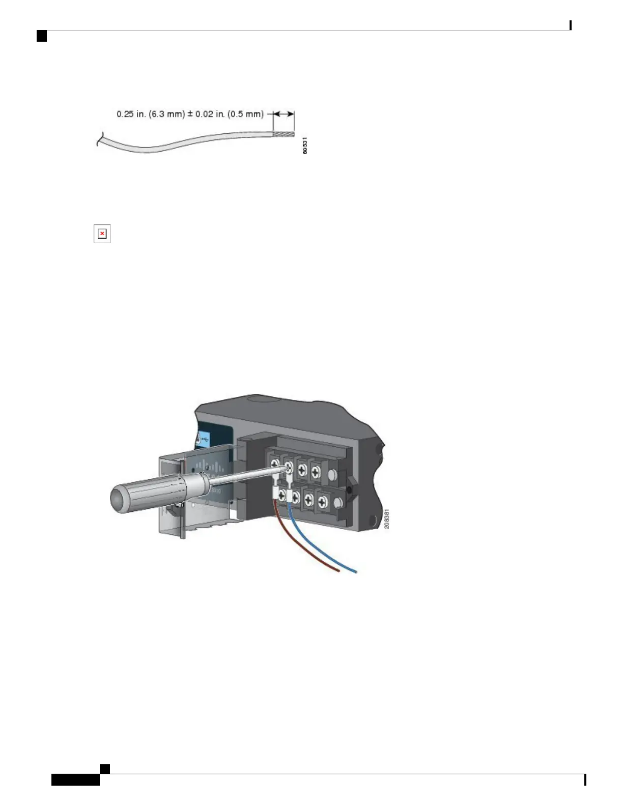
Figure 31: Connecting the Wires to the High-Voltage AC Power (PSU1)
b) DC Power Connection
Connect the positive wire into the terminal screw labeled “ +”, and the negative wire into the terminal screw labeled
“ – ”.
c) Low-voltage DC Power-Supply Module
Connect the wires to the terminals labeled Lo.
d) High-voltage DC Power-Supply Module
Connect the wires to the terminals labeled Hi.
Cisco IE 4010 Switch Hardware Installation Guide
46
Power Supply Installation
Wiring the Power Source
 Loading...


