Ensure that you cannot see any wire lead. Only wire with insulation should extend from the terminal
screw.
Note
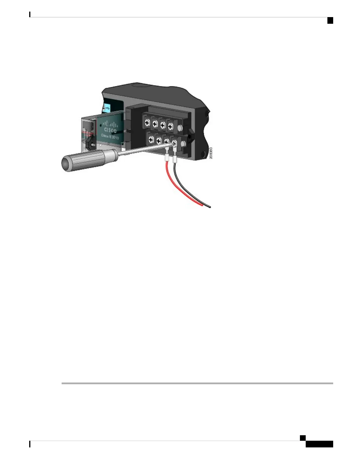
Figure 32: Connecting the Wires to the Low-Voltage DC Power (PSU2)
Step 8 Torque the captive screws (above the wires) to 8.5 in-lb (± 0.5 in-lb).
Step 9 Complete the power connection:
a) AC Power Connection
Connect the other end of the line wire (the one connected to L) to the line terminal on the AC-power source, and
connect the other end of the neutral wire (the one connected to N) to the neutral terminal on the AC power source.
b) DC Power Connection
Connect the other end of the positive wire (the one connected to “ +”) to the positive terminal on the DC-power
source, and connect the other end of the negative wire (the one connected to “ –”) to the negative terminal on the
DC power source.
Ensure that you cannot see any wire lead. Only wire with insulation should extend from the terminal
screw.
Note
If you have two power supplies, repeat steps 1 through 10.
Step 10 Close the power-input terminal cover.
Step 11 Use a ratcheting torque screwdriver to torque the screw to 7 in-lb (± 1 in-lb).
Step 12 Turn on the power at the AC or DC circuit.
Step 13 Verify that the PSU1 or PSU2 LED on the switch and PSU OK LED on the power-supply module are green.
See the switch software guide for information on how to configure the power supply settings.
Cisco IE 4010 Switch Hardware Installation Guide
47
Power Supply Installation
Wiring the Power Source
 Loading...


