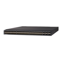
Step 3 Log into UCS Manager and verify the state of the fabric interconnect, either active or subordinate. From the
CLI, enter the show cluster extended-state command. High availability (HA) should be running in UCS
Manager.
Example:
FI-A# show cluster extended-state
Cluster Id: 0x537d0580bf9911e0-0x8955000decd07984
A: UP, PRIMARY
B: UP, SUBORDINATE
A: memb state UP, lead state PRIMARY, mgmt services state: UP
B: memb state UP, lead state SUBORDINATE, mgmt services state: UP
heartbeat state PRIMARY_OK
INTERNAL NETWORK INTERFACES:
eth1, UP
eth2, UP
HA READY <<<<<<<<<<<<<←---------------- HA is READY
Detailed state of the device selected for HA storage:
Chassis 1, serial: FOX1344G1R1, state: active
Chassis 2, serial: FOX1318GDKR, state: active
FI-A#
Step 4 Back up the software configuration.
Step 5 Use the fabric evacuation procedure on the subordinate fabric interconnect to ensure there is no data traffic
impact during the hardware replacement.
Step 6 Power down the subordinate fabric interconnect by unplugging it from the power source.
Example:
FI-A# show cluster extended-state
Cluster Id: 0x537d0580bf9911e0-0x8955000decd07984
A: UP, PRIMARY
B: DOWN, INAPPLICABLE
A: memb state UP, lead state PRIMARY, mgmt services state: UP
B: memb state DOWN, lead state INAPPLICABLE, mgmt services state: DOWN
heartbeat state SECONDARY_FAILED
INTERNAL NETWORK INTERFACES:
eth1, DOWN
eth2, DOWN
HA NOT READY
Peer Fabric Interconnect is down
Detailed state of the device selected for HA storage:
Chassis 1, serial: FOX1344G1R1, state: active
Chassis 2, serial: FOX1318GDKR, state: active
FI-A#
Step 7 Disconnect the cables from the front and back of the fabric interconnect and remove it. Follow the instructions
in this section for removing a fabric interconnect.
Step 8 Install the replacement fabric interconnect. Follow the instructions in this section for installing the fabric
interconnect.
Step 9 Connect the management and console cables to the replacement fabric interconnect.
Step 10 Connect the L1/L2 cables that were disconnected to the replacement fabric interconnect.
Cisco UCS 6454 Fabric Interconnect Hardware Installation Guide
39
Replacing Components
Replacing a Fabric Interconnect

 Loading...