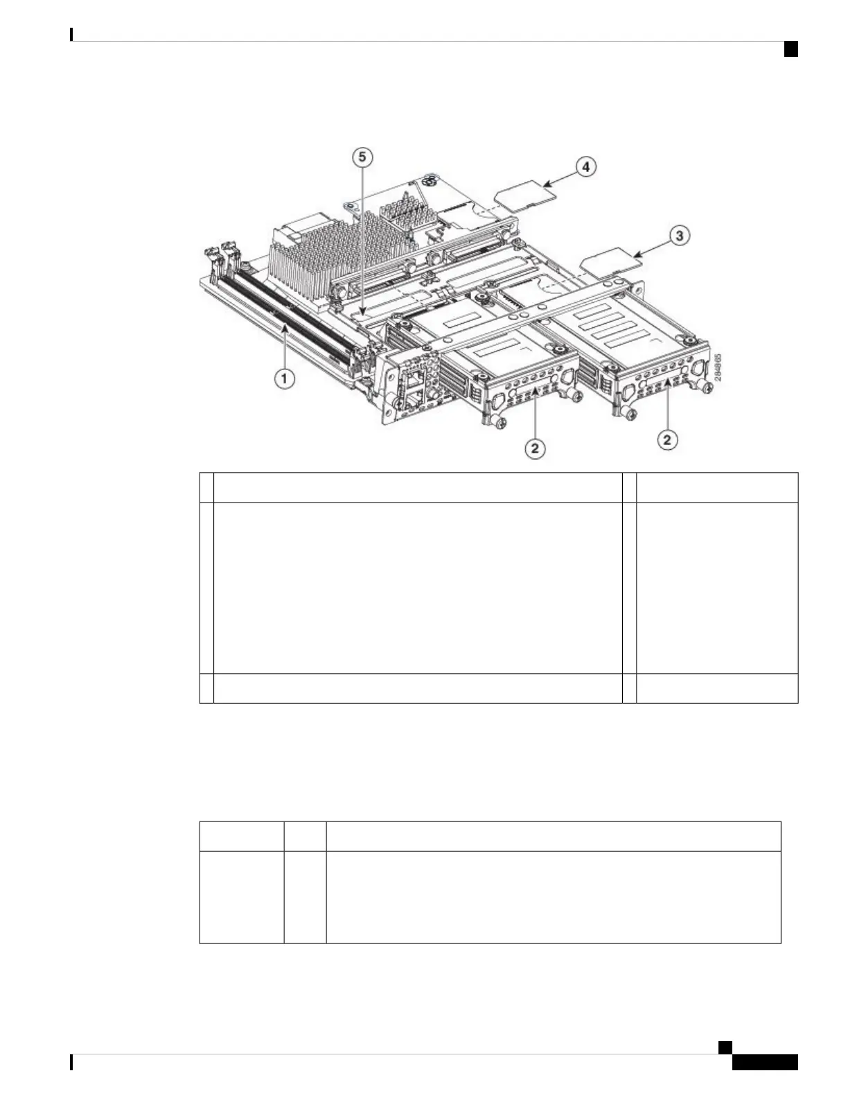
Figure 4: Internal Components of the Single-Wide E-Series Server
HDD2Memory DIMM slots1
SD1
The SD1 card is
interfaced
directly to the
Intel server.
Note
4SD0
The SD0 card contains the Cisco Integrated Management
Controller (CIMC) software and must always be present.
Note
Do not swap SD cards between UCS E-Series Servers. See the
“Recovering from a Faulty SD Card” section in the CLI
Configuration Guide for the Cisco UCS E-Series Servers and
the Cisco UCS E-Series Network Compute Engine Integrated
Management Controller.
Caution
3
CMOS battery (located under the hard drive tray)5
Single-Wide E-Series Server and the SM E-Series NCE LEDs
The following table lists the single-wide E-Series Server and the SM E-Series NCE LEDs and describes the
LED colors and states.
Table 15: Single-Wide E-Series Server and SM E-Series NCE LEDs
StateColorLED
Status of the hard drive activity:
• Steady—Hard drive is present.
• Blinking—Active.
• Off—Inactive or there is no power supplied to the CPU.
GreenHDD 0 ACT
Cisco UCS E-Series Servers and the Cisco UCS E-Series Network Compute Engine Hardware Installation Guide
19
Single-Wide E-Series Server and the SM E-Series NCE LEDs