EasyManuals Logo

Cisco VG310 User Manual

Cisco VG310
96 pages
To Next Page IconTo Next Page
To Previous Page IconTo Previous Page
Page #52 background imageLoading...
Page #52 background image
Connecting a Battery to a DC-Powered Chassis
The following figure shows a setup that uses an external battery. This is one of the many possible setups.
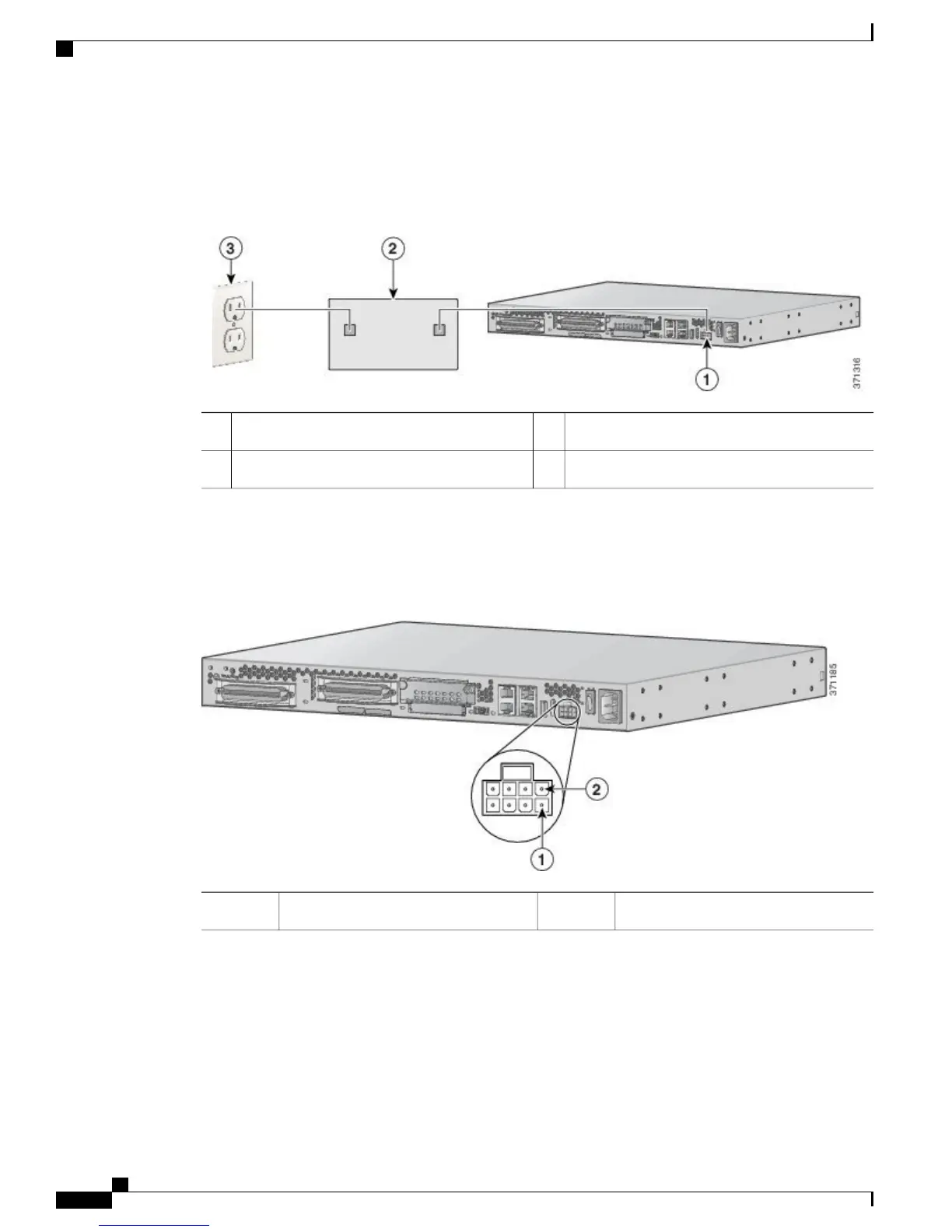
Figure 15: Connecting a Battery to a DC-Powered Chassis
AC wall plug3DC plug1
Battery2
Connect the battery to the DC input connector on your Cisco VG310 or Cisco VG320. The following figure
shows the DC power connector.
Figure 16: +12V DC Power Connector
Pin 52Pin 11
Pinouts for the DC Power Connector
The following table provides information about the pinouts for the DC power connector on Cisco VG310 and
Cisco VG320.
Cisco VG310 and Cisco VG320 Voice Gateways Hardware Installation Guide
40 OL-31292-01
Installing the Cisco VG310 and Cisco VG320 Voice Gateways
Connecting the Chassis to a +12V DC Power Supply

Table of Contents

Other manuals for Cisco VG310

Questions and Answers:

Question and Answer IconNeed help?

Do you have a question about the Cisco VG310 and is the answer not in the manual?

Cisco VG310 Specifications

General IconGeneral
Number of Ports24 FXS ports
Network ProtocolsSIP, MGCP, H.323
Form FactorRack-mountable
Operating Temperature32 to 104°F (0 to 40°C)
Storage Temperature-4 to 149°F (-20 to 65°C)
Power SupplyAC 100 to 240 VAC, 50 to 60 Hz
Ethernet Ports2 x 10/100/1000 Ethernet ports
Humidity10 to 90% non-condensing
ComplianceFCC, CE, UL

Related product manuals