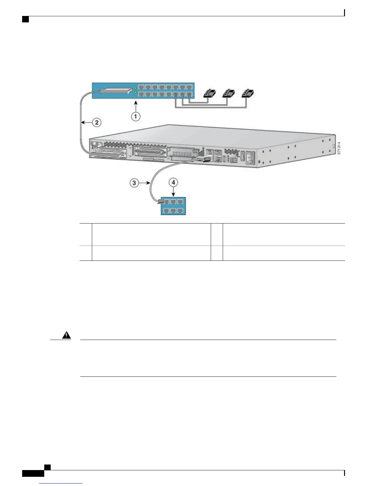
Figure 17: WAN and Voice Connections
RJ-45 cable (through a patch panel) to central
office
3Distribution panel1
Network demarcation4RJ-21 cable2
Connecting the Analog Voice Interface to a Distribution Panel
Before You Begin
Make sure that you have an RJ-21 cable with Amphenol 50-pin connectors.
For information on RJ-21X/CA21A pinouts, see Cable Specifications and Information, on page 69.
This equipment contains a ring signal generator (ringer), which is a source of hazardous voltage. Do not
touch the RJ-11 (phone) port wires (conductors), the conductors of a cable connected to the RJ-11 port,
or the associated circuit-board when the ringer is active. The ringer is activated by an incoming call.
Statement 1042
Warning
Cisco VG310 and Cisco VG320 Voice Gateways Hardware Installation Guide
46 OL-31292-01
Installing the Cisco VG310 and Cisco VG320 Voice Gateways
Connecting the Analog Voice Interface to a Distribution Panel