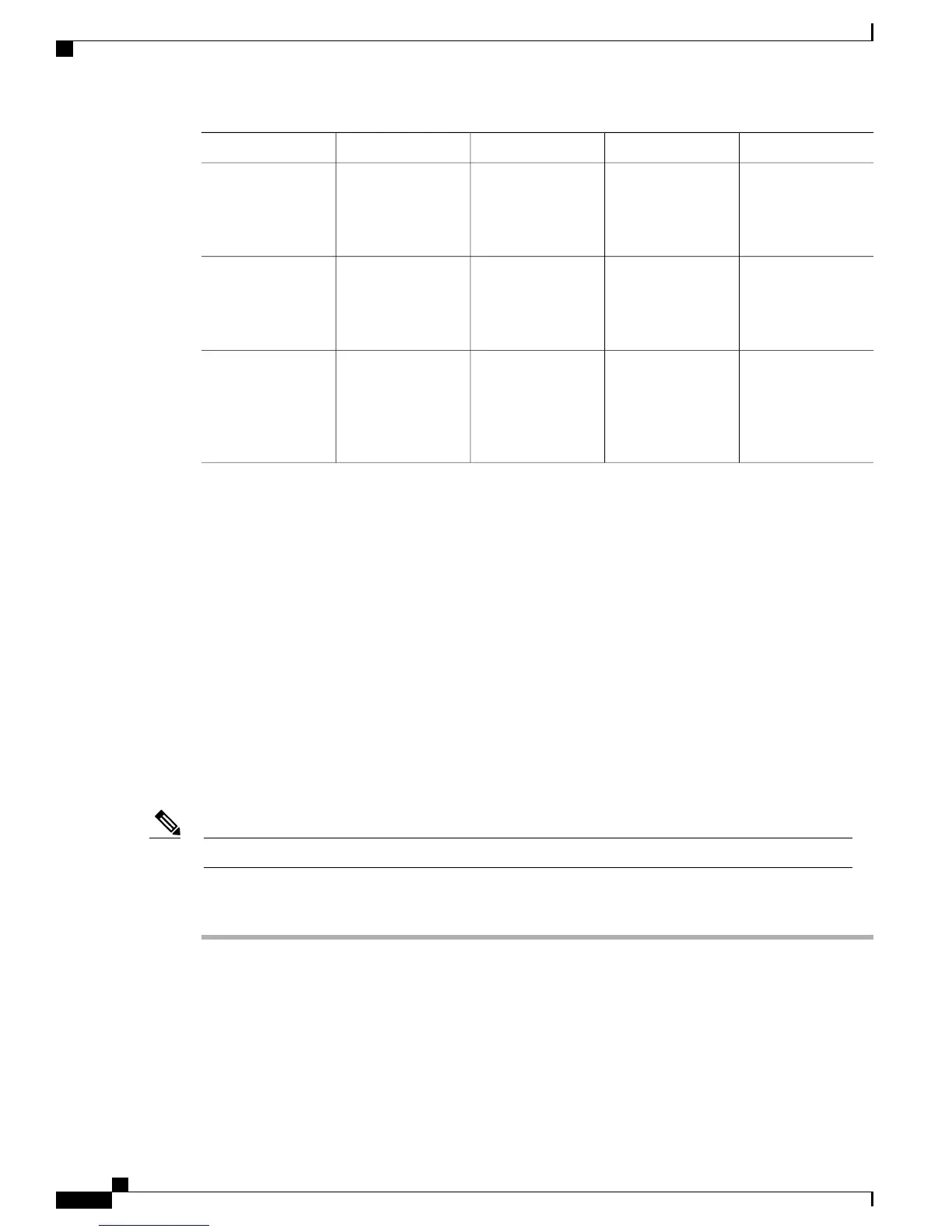
Pinout InformationInterface ToConnector/CablePort ColorVoice Gateway Port
Auxiliary Port
Signals and
Pinouts, on page
71
ModemRJ-45/RolloverBlackAuxiliary
Gigabit Ethernet
Connector Pinouts
(RJ-45), on page
73
LANRJ-45/Gigabit
Ethernet
YellowGigabit Ethernet
Analog Voice RJ-21
Pinouts, on page
77
Distribution panel
for analog
telephone, fax,
PBX, or central
office line
RJ-21X/
50-conductor
GrayAnalog voice
multiport
Remote Terminal Connections (If Applicable)
If you are configuring a voice gateway from a remote location, connect the modem and the remote PC or
terminal to the telephone network as described in this section.
Connecting to a Modem
To connect the local modem and the remote modem to live telephone outlets, use standard telephone cables.
Connecting to a Remote PC
Before You Begin
The remote PC must be running terminal emulation software.Note
Procedure
Step 1
Connect the remote PC to the modem.
Step 2
Set the PC terminal emulation software requirements as follows:
•
9600 baud
•
8 data bits
•
1 stop bit
Cisco VG310 and Cisco VG320 Voice Gateways Hardware Installation Guide
48 OL-31292-01
Installing the Cisco VG310 and Cisco VG320 Voice Gateways
Remote Terminal Connections (If Applicable)