C-3
Catalyst 3560 Switch Hardware Installation Guide
OL-6337-07
Appendix C Connecting to DC Power
Connecting to DC Power
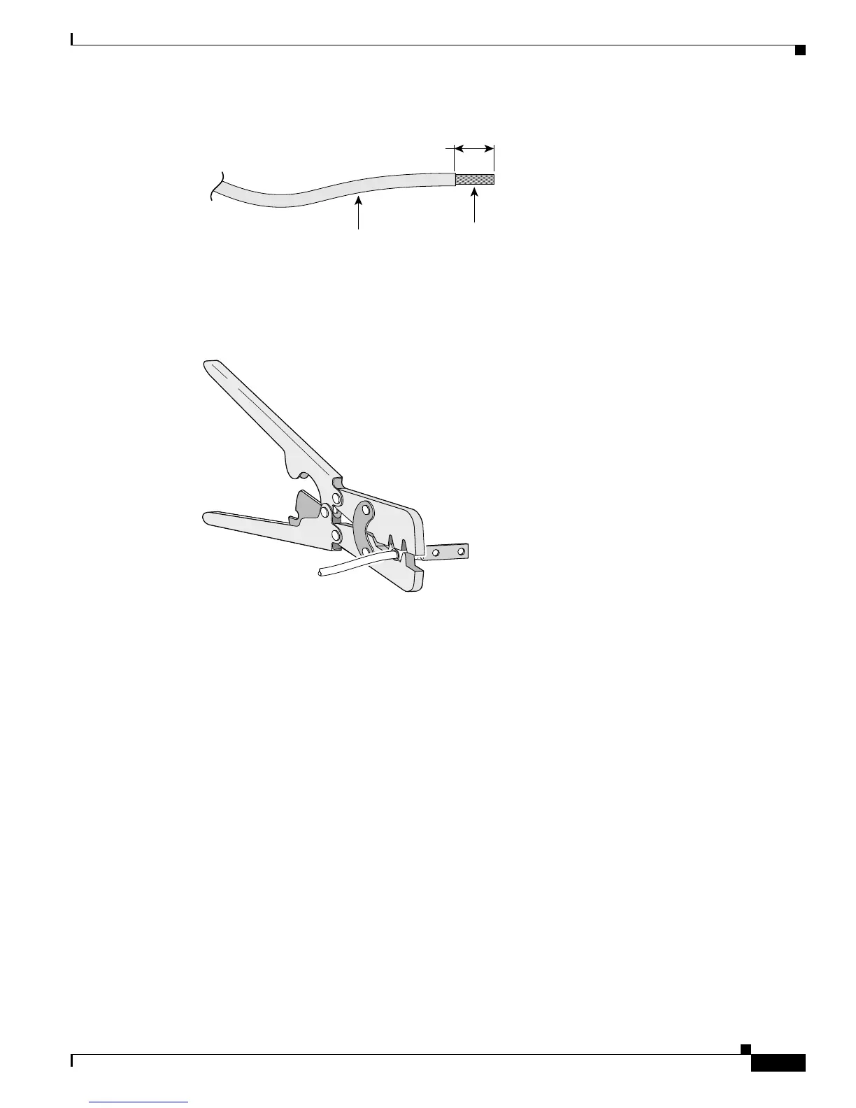
Figure C-1 Stripping the Ground Wire
Step 3 Slide the open end of the ground lug over the exposed area of the 6-gauge wire.
Step 4 Using a Panduit crimping tool, crimp the ground lug to the 6-gauge wire, as shown in Figure C-2.
Figure C-2 Crimping the Ground Lug
Step 5 Use the two number-10-32 screws to attach the ground lug and wire assembly to the switch rear panel
ground connector, as shown in Figure C-3. If you are using an RPS, connect the ground lug as shown in
Figure C-4.
Step 6 Using a ratcheting torque screwdriver, torque each ground-lug screw to 15 lbf-in. (240 ozf-in.)
Insulation
Wire lead
0.5 in. (12.7 mm)
±
0.02 in. (0.5 mm)
60528
 Loading...


