1-16
Catalyst 3560 Switch Hardware Installation Guide
OL-6337-07
Chapter 1 Product Overview
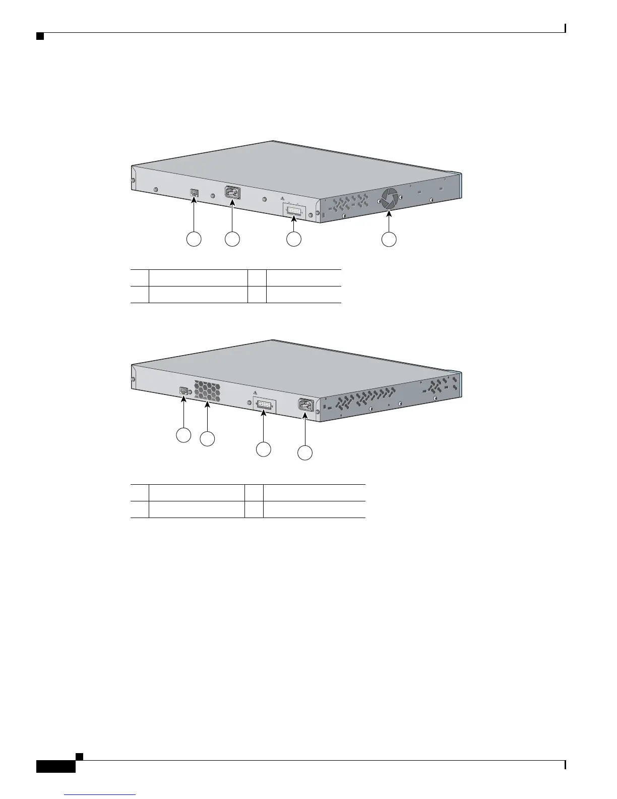
Rear Panel Description
The switch rear panel has an AC power connector, an RPS connector, and an RJ-45 console port. (See
Figure 1-14, Figure 1-15, and Figure 1-16 for examples of the Catalyst 3560 rear panels.)
Figure 1-14 Catalyst 3560-24PS and 3560-48PS Switch Rear Panel
Figure 1-15 Catalyst 3560G-24PS, 3560G-48PS, 3560G-24TS, and 3560G-48TS Switch Rear Panel
1 RJ-45 console port 3 RPS connector
2 AC power connector 4 Fan exhaust
RATING
100-200V ~
5.0A-2.5A, 50-60 HZ
CO
NSOLE
DC INPUTS FOR REMOTE
POWER SUPPLY
SPECIFIED IN MANUAL
+12v @7.5A -48 @7.8A
97914
1 2 3
4
1 RJ-45 console port 3 RPS connector
2 Fan exhaust 4 AC power connector
CONSOLE
DC INPUTS FOR REMOTE
POWER SUPPLY
SPECIFIED IN MANUAL
119678
1
2
3
4

 Loading...


