3-13
Catalyst 3560 Switch Hardware Installation Guide
OL-6337-07
Chapter 3 Switch Installation (8- and 12-Port Switches)
Installing the Switch
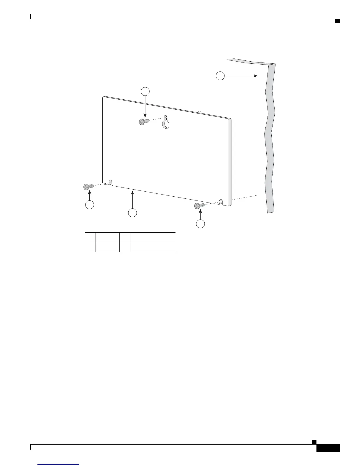
Figure 3-5 Installing the Mounting Screws on a Wall
Step 3 Peel the adhesive strip off the bottom of the screw template.
Step 4 Attach the screw template to the wall.
Step 5 Use a 0.144-inch (3.7 mm) or a #27 drill bit to drill a 1/2 inch (12.7 mm) hole in the three screw
template slots.
Step 6 Insert three screws in the slots on the screw template, and tighten until they touch the top of the
screw template.
Step 7 Remove the screw template from the wall.
1 Wall 3 Screw template
2 Screws
CABLE SIDE ENTRY
THIS SIDE AWAY FROM
MOUNTING SURFACE
2
3
2
2
1
157828
 Loading...


