3-5. Disassembly, Reassembly and Lubrication
CLP-621 & CLP-631 3-38
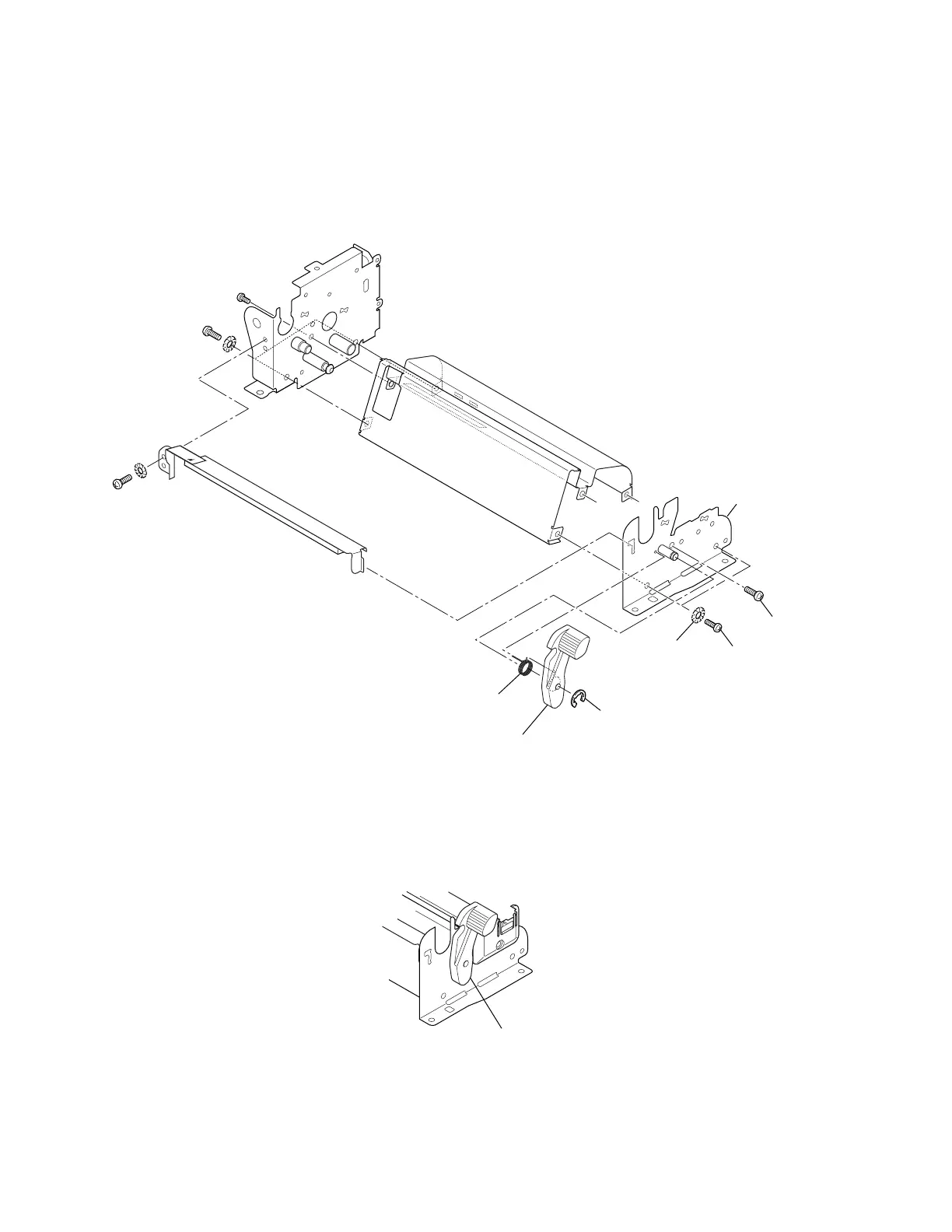
3-5-23. Head Lock Lever and Main Plate R SA
1. Remove the Mechanism Unit. Refer to 3-5-13 “Mechanism Unit and Case L”.
2. Remove 2 screws (BH (N), M3x6), 2 washers (EXT. T, 3 (NI)) and 1 screw (PH, M3x6), and
detach the Main Plate R Unit.
3. Disengage 1 E-Ring and detach the Head Lock Lever and the Head Lock Spring from the Main
Plate R SA.
BH (N), M3x6
PH, M3x6
E-Ring, 2.5
Lever, Head Lock
Spring, Head Lock
EXT. T, 3 (NI)
SA, Main Plate R
Note on reassembling:
• When assembling the Head Lock Lever, hook the Head Lock Spring as shown. (One end is
inserted into the groove of the Head Lock Lever and the other end into the hole.) Also, the Head
Lock Lever should be assembled on the Main Plate R SA as shown in the figure.
Lever, Head Lock