3-5. Disassembly, Reassembly and Lubrication
3-39 CLP-621 & CLP-631
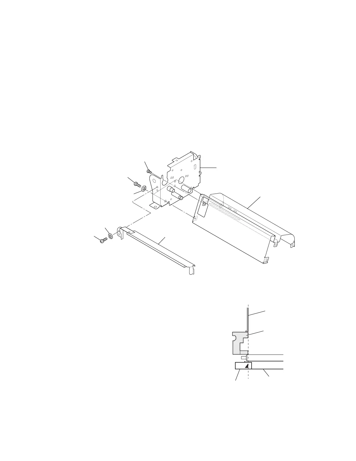
3-5-24. Main Frame, Main Plate L SA and Plate Peeler SA
1. Remove the Mechanism Unit. Refer to 3-5-13 “Mechanism Unit and Case L”.
2. Remove the PF Unit. Refer to 3-5-17 “Head Block and PF Unit”.
3. Remove the Motor SA. Refer to 3-5-20 “Motor SA”.
4. Remove the Sensor Guide Shaft (with the Sensor Holder L SA and the Paper Set Guide).
Refer to steps 1 to 4 in 3-5-21 “Reflective Sensor PCB SA”.
5. Remove 3 gears. Refer to 3-5-22 “Gears”.
6. Remove the Main Plate R Unit. Refer to steps 1 and 2 in 3-5-23 “Head Lock Lever and Main
Plate R SA”.
7. Remove 2 screws (BH (N), M3x6), 2 washers (EXT. T, 3 (NI)) and 1 screw (NO.0, PH (#1),
M2.6x6), and detach the Main Frame.
8. Remove 1 screw (BH (N), M3x6) and 1 washer (EXT. T, 3 (NI)) and detach the Plate Peeler SA
from the Main Plate L SA.
Frame, Main
SA, Main Plate L
BH (N), M3x6
NO.0, PH (#1), M2.6x6
SA, Plate Peeler
EXT. T, 3 (NI)
BH (N), M3x6
EXT. T, 3 (NI)
Note on reassembling:
• Media-path left-edge alignment when assembling the Plate
Peeler SA:
When assembling the Plate Peeler SA, align the arrow mark
on the Plate Peeler SA with the media contacting surface of
the Head Wire Cover as shown.
Also, when you stick a new Mark Label, align its arrow mark
with the media contacting surface of the Head Wire Cover.
(When assembling the Mechanism Unit, the media guide end
of the Head Wire Cover should be aligned with the chassis
plate of the Main PCB Block (as explained in 3-5-13
“Mechanism Unit”). Then, the media-path left-edges are
aligned on the basis of the Mark Label.
Cover, Head Wire
(Media Guide End)
Mark Label
Main PCB Block
(Media Guide End)
SA, Plate Peeler
Align.