3-5. Disassembly, Reassembly and Lubrication
3-13 CLP-621 & CLP-631
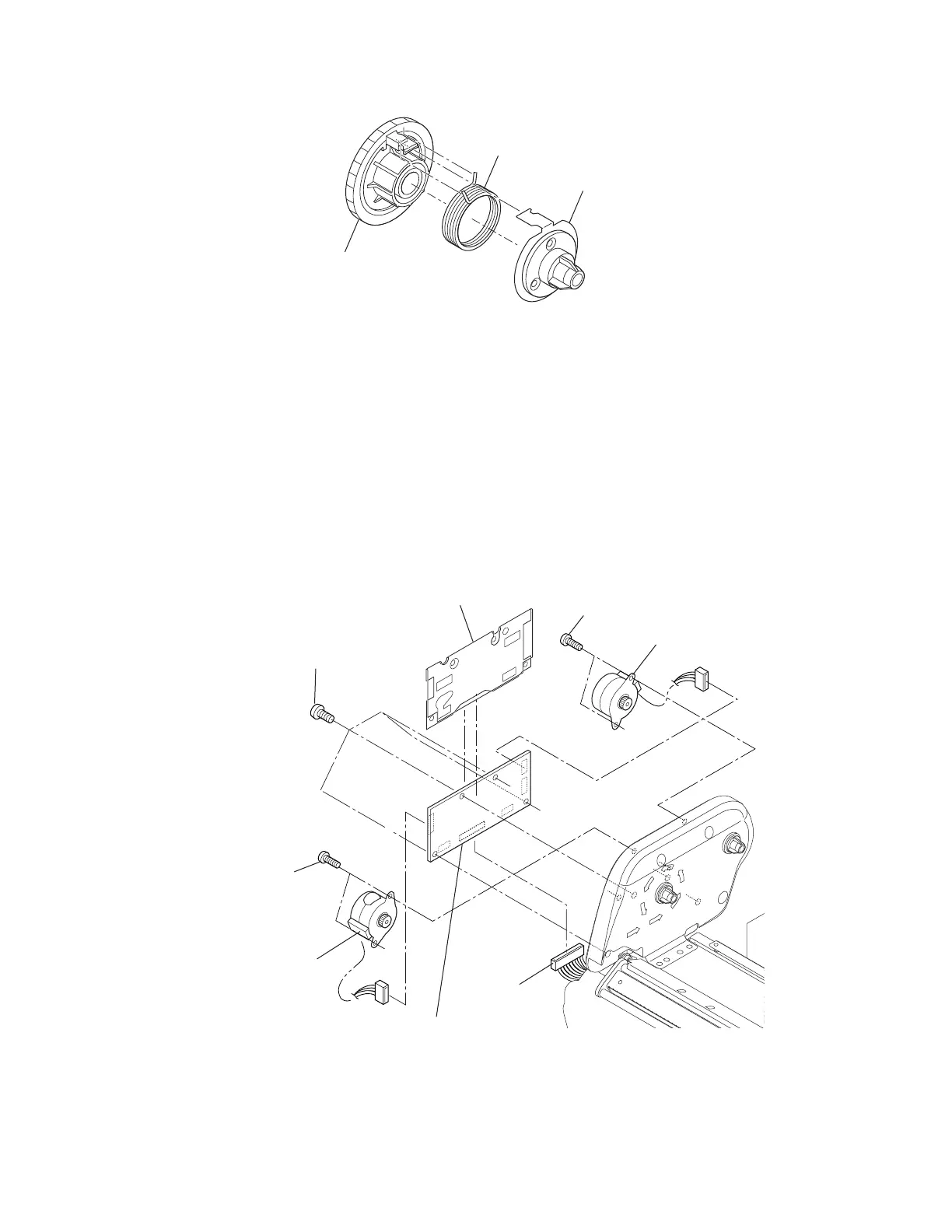
• Assemble the Holder R Shaft SA, the Ribbon Return Spring, and Ribbon Gear 5F/5R as follows:
Gear 5F, Ribbon/
Gear 5R, Ribbon
Spring, Ribbon Return
SA, Holder R Shaft
• Apply FLOIL G-474C to the parts (gears and shafts) shown by the
marks.
3-5-5. Ribbon Motor F/R SA and Ribbon Main PCB SA
1. Remove the Top Cover SA and remove the Ribbon Unit Fan SA2. Refer to Step 2 (Normal
way) in 3-5-2-(1) “Removing the Case U without detaching the Ribbon Unit (Normal way)”.
2. Disconnect 1 connector (CN701) from the Ribbon Main PCB.
3. Remove 2 screws (PH, M2.6x3), disconnect 1 connector, and detach the Ribbon Motor F SA.
4. Remove 2 screws (PH, M2.6x3), disconnect 1 connector, and detach the Ribbon Motor R SA.
5. Remove 5 screws (BH, M3x6 (NI)), and detach the Ribbon Main PCB SA and the Ribbon
Board Insulator.
Insulator, Ribbon Board
PH, M2.6x3
SA, Ribbon Motor R
PH, M2.6x3
SA, Ribbon Motor F
SA, Ribbon Main PCB
BH, M3x6 (NI)
(CN701)