3-5. Disassembly, Reassembly and Lubrication
CLP-621 & CLP-631 3-26
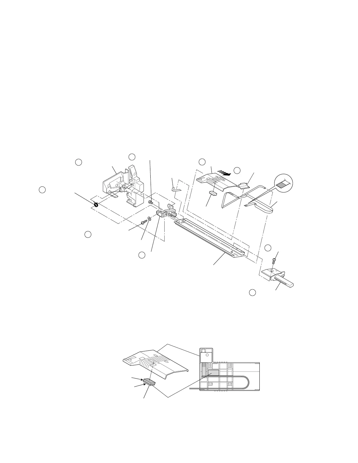
(2) Transparent Sensor Cable SA
1. Remove the Sensor U Unit. Refer to 3-5-15 “Sensor U Unit”.
2. Remove the Transparent Sensor PCB SA. Refer to (1) as above.
3. Remove 1 screw (PHT (PT2T), M2x8) (c) and 1 washer (Plain, 2), and disengage the
Sensor U Unit body from the Head Wire Cover (d). Then, remove the Sensor Frame
Spring (e).
4. Remove 1 screw (PH, M3x6) (f) and detach the Sensor Frame R Cap (g).
5. Remove the Sensor Cable U Cap (h) to set the Transparent Sensor Cable SA free.
6. Remove 2 screws (PH, M2.6x3) (i) and detach the Sensor Frame L Cap (j).
7. Remove the Sensor U Holder (k) by sliding it to the right and detach the Transparent
Sensor Cable SA.
8. Remove the Sensor L Damper from the Sensor U Holder.
9. Peel off the Sensor Cable U Tape from the Sensor Holder U Frame.
8
1
3
4
5
7
6
9
2
Holder, Sensor U
Cap, Sensor Frame R
PH, M3x6
Frame, Sensor Holder U
SA, Transparent
Sensor Cable
Cap, Sensor Cable U
Damper, Sensor L
PHT (PT2T), M2x8
Plain, 2
Cap, Sensor Frame L
PH, M2.6x3
Spring, Sensor Frame
Cover, Head Wire
Tape, Sensor
Cable U
Notes on reassembling:
• When assembling the Sensor L Damper, push it into the Sensor U Holder so that the felt
side can be seen.
[Bottom View]
Holder, Sensor U
Felt part
Rubber part
Damper, Sensor L