Hydraulic / Electric System JAGUAR 8550C TIC
1-8 10/04
1.2 Function
1.2.1 Actuate from
transport to working
position
Caution:
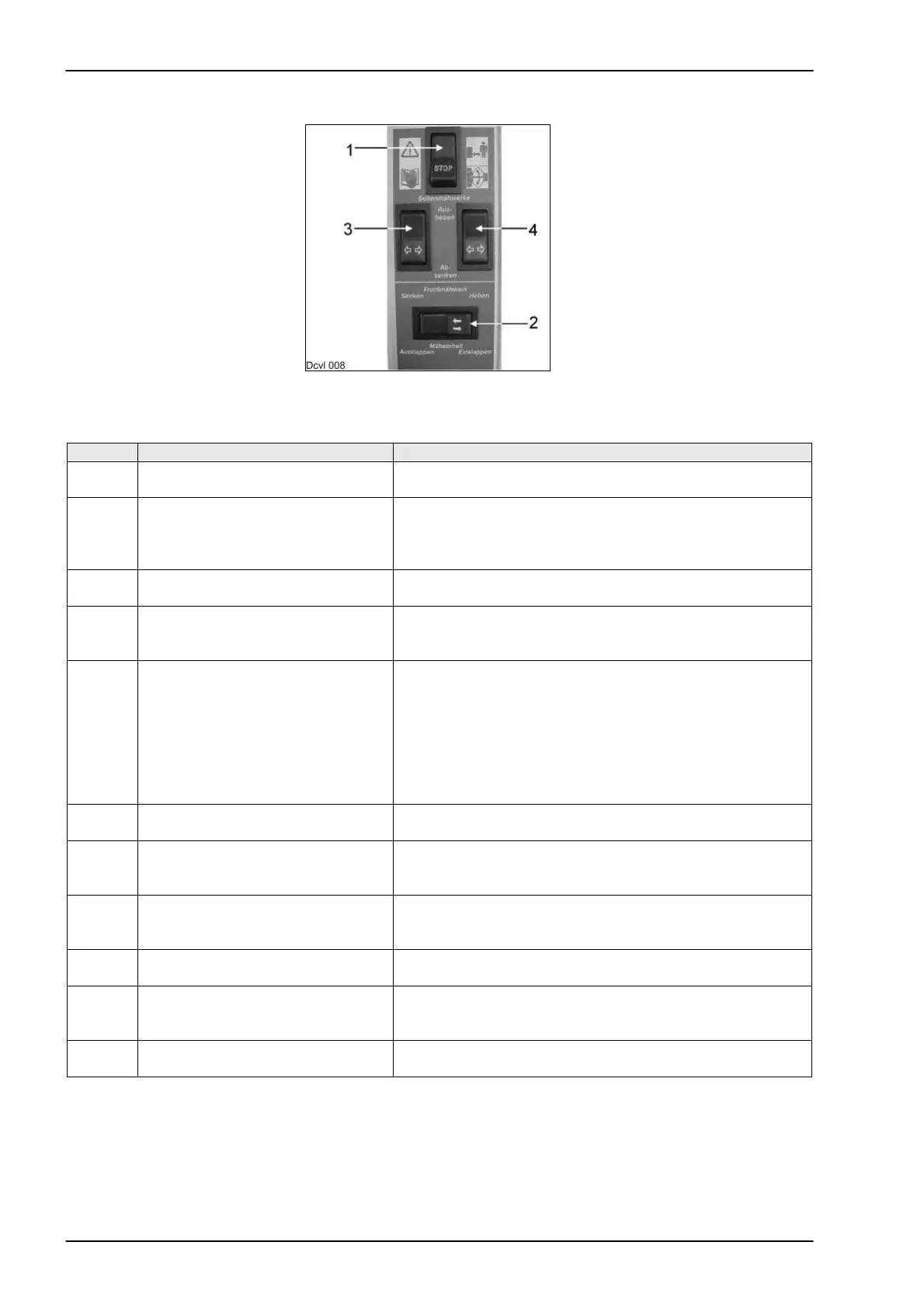
1 = Main switch ON-OFF. Set to OFF when parking the machine.
Step Action Reaction
1 Switch 2 on the CCT is actuated to
the right
Solenoid valve 50 goes to position B.
Volume flow goes to the solenoid valves 71, 72, 73 and 74.
2 Solenoid valve 72 is triggered The applied volume flow goes to cylinder 103.
The front mower unit is raised to its end position = the
pressure rises and oil pressure switch 93 switches at
150 bar.
3 Solenoid valves 70 and 71 are
triggered.
Volume flow goes to the rod spaces of cylinder 91 and 92
via the solenoid valve 71.
4 The displaced volume flow from the
ram top space flows to the tank via
the energized solenoid valve 70.
The side-mounted mower unit are folded in.
The lock can be released.
5 Switch 2 on the CCT is actuated to
the left
Solenoid valve 50 goes to position A.
Solenoid valves 70 and 71 are triggered. This makes
volume flow flow through solenoid valves 70:
into cylinders 82 and 85 (but also the non-return valves 81
and 84).
into cylinders 91 and 92. The side-mounted mower units
are now folded out and the starting protections are
activated.
6 Cylinders travel against their end
stop
Pressure switch 95 switches at a pressure of 150 bar.
7 Solenoid valve 72 is triggered Volume flow from cylinders 103 flows through 72 and
solenoid valve 50 (position A) into the tank. The front
mower unit is lowered.
8 The lower command for the left
mower unit is issued on the control
terminal (switch 3).
Solenoid valve 50 goes to position A.
Solenoid valve 73 is energized.
9 Volume flow from cylinder 100
flows into the tank.
The left mower unit is lowered.
10 The lower command for the right
mower unit is issued on the control
terminal (switch 4).
Solenoid valve 50 goes to position A.
Solenoid valve 74 is energized.
11 Volume flow from cylinder 90 flows
into the tank.
The right mower unit is lowered.
During work, the working pressures of all cylinders are supported by the accumulators 88, 98 and 102. The
lock-up valve units are opened at switch 94 below 80 bar. When the pressure rises to above 85 bar, the
lock-up valve units are closed and the mower units remain in their position. The ground pressure of the
mower units can be seen on pressure gauges 87, 97 and 101.