Hydraulic / Electric System LINER TIC
4-8 10/04
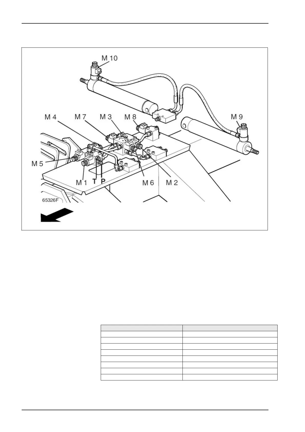
1.1.5 Location of
components
Key to diagram M1 Circulation blocking solenoid valve (master valve)
M2 Lower chassis solenoid valve
M3 Raise chassis solenoid valve
M4 Lower front rotors solenoid valve
M5 Raise front rotors solenoid valve
M6 Front rotors wider solenoid valve
M7 Front rotors narrower solenoid valve
M8 Raise rear rotors solenoid valve
M9 Lower rear rotors solenoid valve
M10 Lower rear rotors solenoid valve
P Pump inlet
T Tank line
Function/valve assignment
Function Valve
Raise front rotors 1 + 5
Lower front rotors 1 + 4
Raise rear rotors 1+ 8
Lower rear rotors 1+ 9 + 10
Raise chassis 1 + 3
Lower chassis 1 + 2
Increase working width 1 + 6
Decrease working width 1 + 7