Hydraulic / Electric System LINER TIC
4-12 10/04
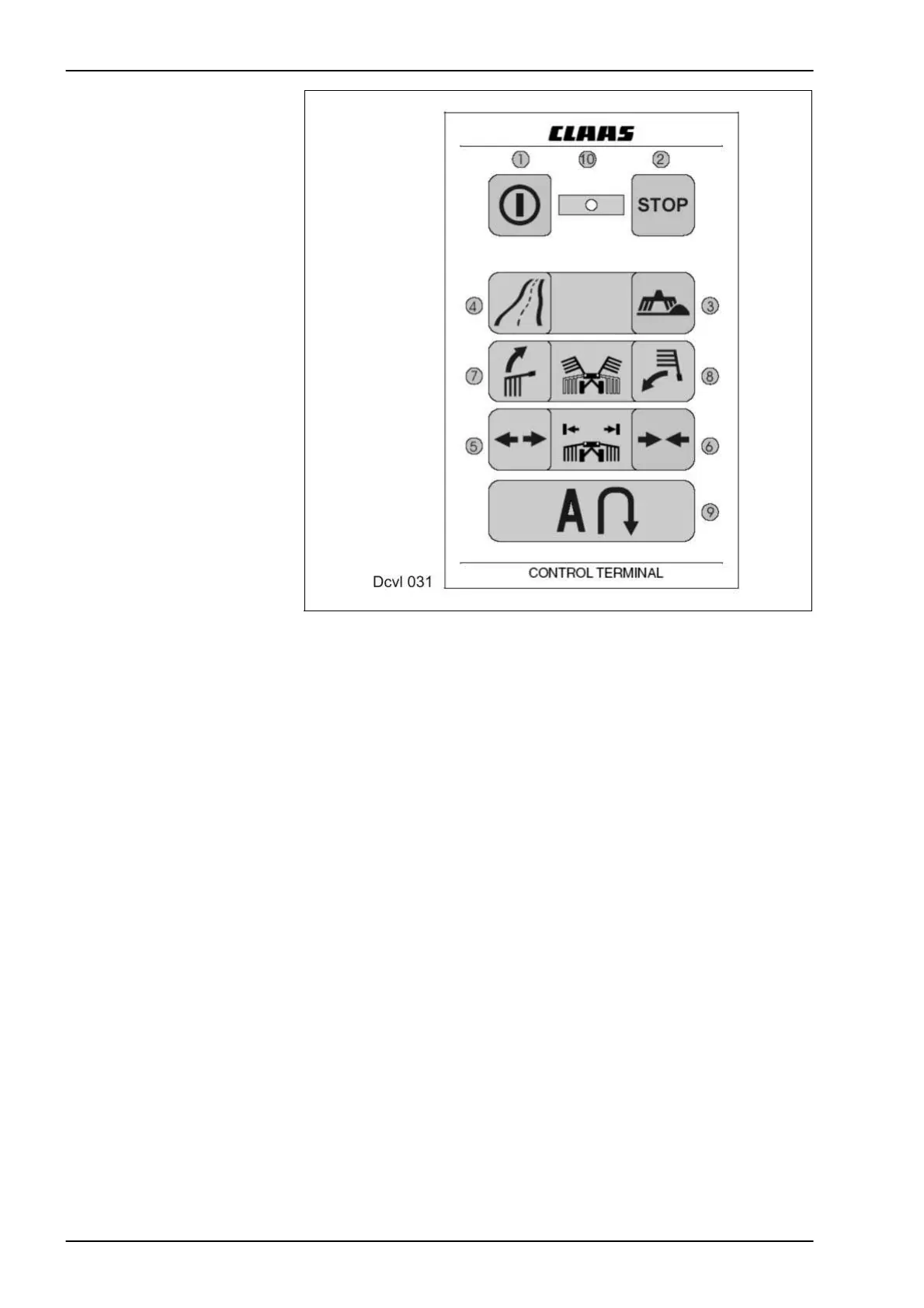
1.3 CCT
LINER 3000
Key to diagram 1 On/Off switch
(press for approx. 3 seconds until LED lights up or goes out)
2 Stop switch (program interruption)
3 Working position switch
4 Transport position switch
5 Swath width front wider switch
6 Swath width front narrower switch
7 Raise front rotors switch
8 Lower front rotors switch
9 Turning area switch
10 LED (light-emitting diode)
After switching on the control terminal, the angle transmitters are
automatically tested:
• LED 10 lights up: no fault
• LED 10 flashing once: front angle transmitter defective.
• LED 10 flashing twice: rear angle transmitter defective.
• LED 10 flashing three times: both angle transmitters defective.