11
5. Installation 5. Installation
Mounting the remote control’s
wall bracket
• Before attaching the wall bracket
to the wall, ensure that the remote
control has radio contact to the
instantaneous water heater from its
designated position.
• The wall bracket of the remote control
can either be attached securely with
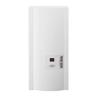
the included adhesive tape, after strip-
ping off the protection film (as shown
in the figureA), on a rigid board (e.g.
tile) or with suitable dowels (Ø 4 mm)
and screws (as shown in the figureB).
• When using the adhesive tape it is not
possible to further adjust the position
because of the strong adherence of
the glue. Therefore, pay attention to
a horizontal alignment when attach-
ing it.
• The remote control is magnetically
retained at the wall bracket.
Note:
Do not expose the remote control to
moisture.
Wandhalter der Funkfern-
bedienung montieren
• Prüfen Sie vor der Montage
des Wandhalters, ob die
Funkfernbedienung an der vorge-
sehenen Position Funkkontakt zum
Durchlauferhitzer aufnehmen kann.
• Der Wandhalter der
Funkfernbedienung kann wahlweise
mit den beiden Klebe streifen nach
Abziehen der Schutzfolien auf eine
feste Unterlage (z.B. Fliese) geklebt
werden (AbbildungA) oder mit geeig-
neten Dübeln (Ø 4 mm) und Schrauben
an der Wand montiert werden
(AbbildungB).
• Bei Verwendung der Klebestreifen ist
nach dem Andrücken keine Positions-
korrektur mehr möglich, da der Kleber
eine sehr hohe Klebkraft besitzt.
Achten Sie daher auf eine waage-
rechte Ausrichtung beim Aufkleben.
• Die Funkfernbedienung wird magne-
tisch am Wandhalter gehalten.
Hinweis:
Die Funkfernbedienung keiner
Feuchtigkeit aussetzten
Abbildung B:
Optionale Montage mit
Dübeln und Schrauben
Figure B:
Optional installation
with dowels and screws
Abbildung A:
Montage mit
Klebestreifen
Figure A:
Installation with
adhesive tape
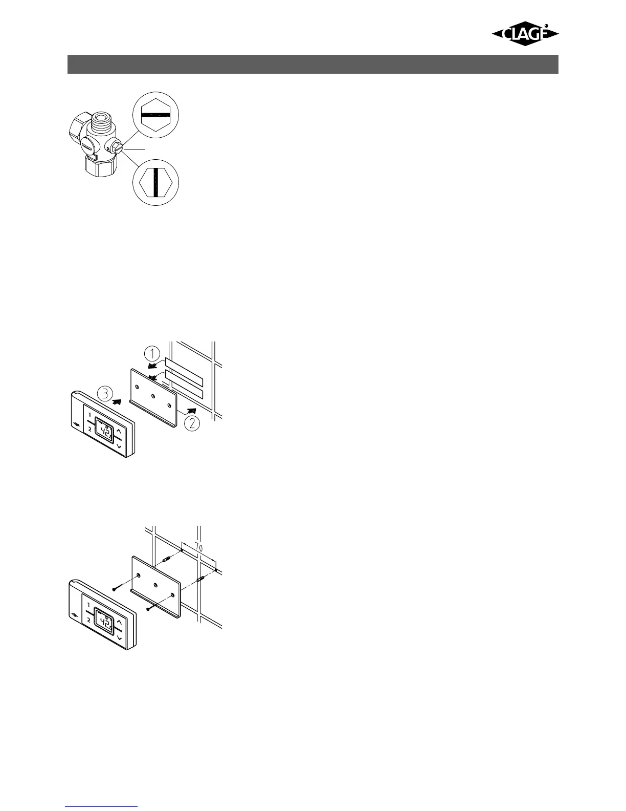
(a)
geschlossen
closed
geöffnet
open
5. Öffnen Sie die Wasser zuleitung und
drehen Sie das Absperr ventil (a) im
Kalt wasser anschluss stück lang sam auf
(Position »geöffnet«). Prüfen Sie alle
Verbindungen auf Dichtigkeit.
6. Öffnen und schließen Sie danach
mehrfach die zugehörige Warm-
wasser armatur bis keine Luft mehr aus
der Leitung austritt und der Durchlauf-
erhitzer luftfrei ist.
5. Open the water supply line to the unit
and slowly open (position “open“) the
shut-off valve (a) in the cold water
connection piece. Check all connec-
tions for leaks.
6. Next, open and close the hot water
tapping valve several times until no
more air emerges from the line and
all air has been eliminated from the
instantaneous water heater.


 To Next Page