Section 6. Planned Maintenance
6.7
11
10
9
8
718051
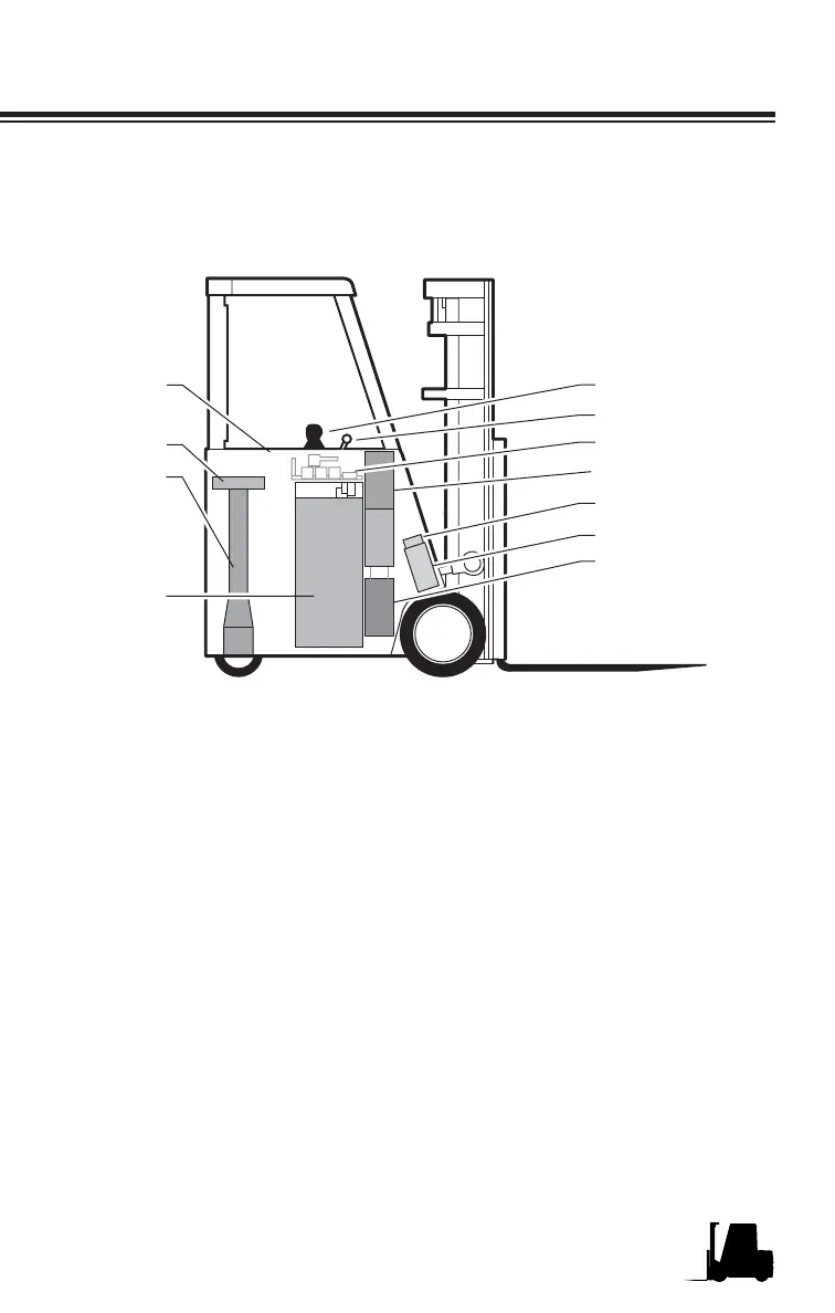
1. Multi Function Handle
2. Battery Disconnect
3. Traction Control Panel
4. Lift Pump and Motor
5. Parking Brakes
6. Drive Motors
7. Sump Tank
8. Battery
9. Steer Axle and Housing
10. Steer Actuator
11. Steer Handle
Use the illustration below to help you locate components included in
the PM procedures.
1
2
3
4
5
6
7
Component Locations
Major Component Location
The truck shown above is a typical representation of a CLARK electric
counterbalanced stand up lift truck. Your model may very slightly.