750-392
CBEX-DE
1-7
Component Locations
Combination gas/oil burners include equipment for each fuel, with a fuel selector switch mounted in the control
panel. Regardless of which fuel is used, the burner operates with full modulation within its rated operating range.
The burner returns to minimum firing position for ignition.
The flame safeguard includes a flame detector to supervise both oil and gas flames, and to shut the burner down
in the event of loss of flame. The burner sequence provides a pre-purging period, proving of the pilot and main
flame, and a period of continued blower operation after shutoff to postpurge the boiler of all unburned fuel vapor.
Other safety controls shut down the burner under low-water conditions, excess steam pressure, or water tem-
perature.
Safety interlock controls include combustion and atomizing air proving switches and, depending upon the fuel
and insurance carrier requirements, controls that prove the presence of adequate fuel pressure.
The sequence of burner operation from startup through shutdown is governed by the program relay in conjunc-
tion with the operating, limit and interlock devices. The devices are wired into the circuitry to provide safe opera-
tion and protect against incorrect operating techniques.
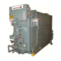
All CBEX-DE boilers have the burner assembly integral with the front head. The burner drawer can be removed as
a unit, or the entire head may be swung open for inspection and maintenance.
Combustion air is provided by a centrifugal blower located in the front head.
Filtered primary air for atomizing fuel oil is furnished independently of combustion air by an air compressor. The
burner control circuit operates on 115 volt, single phase 60 Hz (or 50 Hz when equipped) alternating current.
The forced draft fan motor is generally operated on 3-phase service at the available main power supply voltage.
In addition to the standard basic controls supplied, other devices may be required to meet specific requirements
of an insurance carrier or local code.
Refer to the wiring diagram prepared by Cleaver-Brooks for your installation to determine the specific controls in
the burner and limit control circuits.
 Loading...


