750-392
CBEX-DE
4-9
Firing Preparations for No. 2 Oil (Series 100, 200)
4.7 — Firing Preparations for No. 2 Oil (Series 100, 200)
Prior to initial firing, oil flow and pressure should be established and
verified. Atomizing air pressure should also be verified.
If the burner is a combination fuel model, be certain that the main gas
shutoff cock is closed and set the gas/oil selector switch to “oil.”
Insert the burner drawer gun into its most forward position and latch
it in place, closing the oil drawer switch.
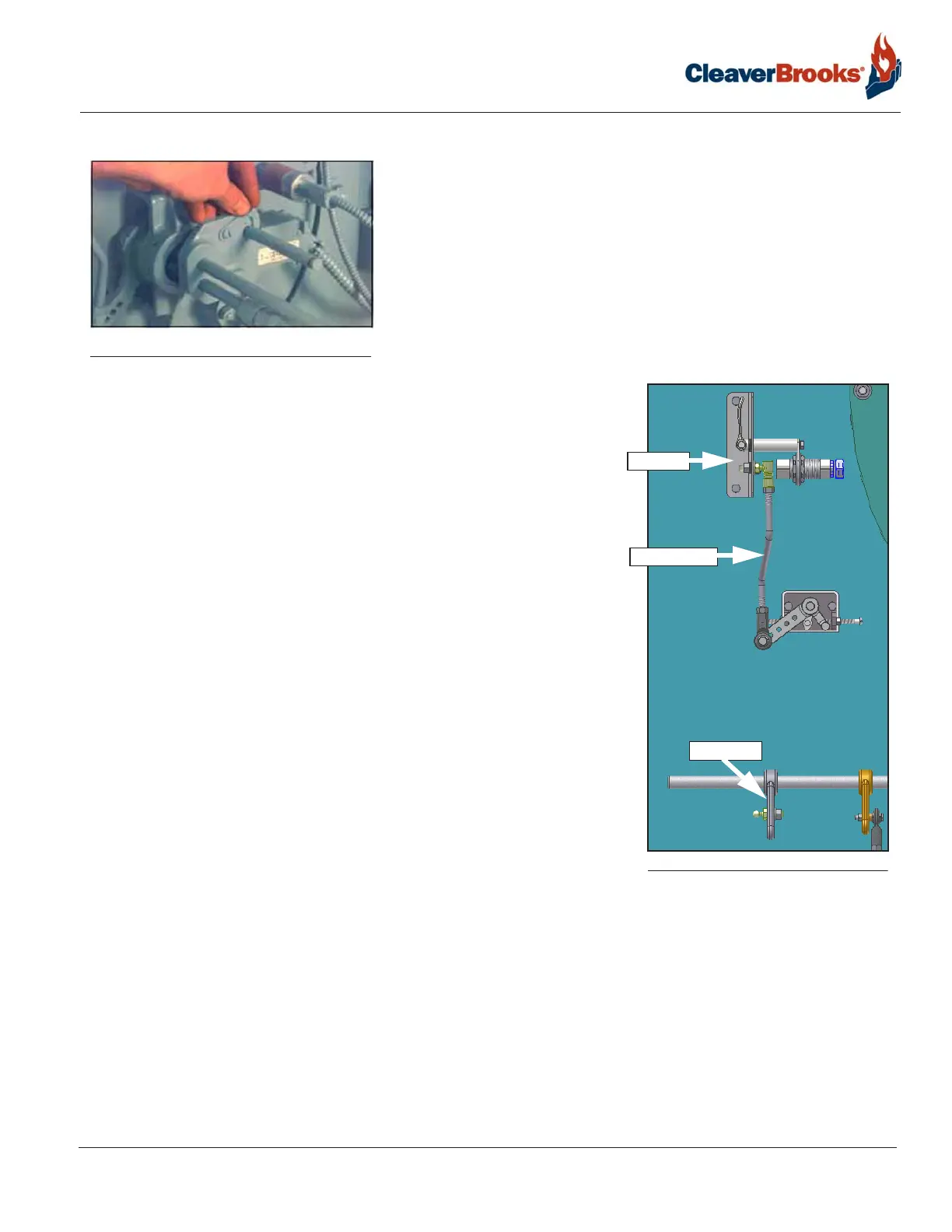
For gas/oil burners with single point positioning, the FGR drive linkage
will need to be removed from the jackshaft FGR drive arm and attached
to the proximity switch mounting bracket (see illustration). The proximity
switch will ensure that the linkage is in the correct position and the FGR
valve is closed during oil firing.
If the oil supply tank is located above the level of the pump and flow to
the pump is by gravity, then it will usually be necessary to vent the suc-
tion line to allow oil to fill the line. Venting the suction line can generally
be accomplished by cracking a union fitting, or by opening the cap of the
oil strainer using care to prevent spillage of oil. Tighten the fitting or the
cap as soon as oil flow appears.
If the oil supply tank is below the level of the oil pump, it is mandatory
that the suction line to the pump be completely filled with oil prior to
starting the pump to avoid the possibility of damage to the pump gears.
Non-lubricating fluids such as kerosene should not be used for priming.
Prior to priming the suction line and the initial start, check to make cer-
tain that all plugs, connections, etc., have been securely tightened to pre-
vent leaks.
If the fuel oil supply originates from a pressurized loop, it is assumed that
the pressure of the loop will be at a minimum of 75 psi. Under these con-
ditions, the relief valve at the terminal block should be adjusted to the
point where it becomes inoperative (or removed and openings plugged).
To render inoperative, turn the adjusting screw in as far as possible.
A standardly equipped boiler has a selector switch incorporated in the oil pump motor starter. Momentarily ener-
gize the starter to check for proper pump rotation. With the rotation verified, operate the pump to determine that
oil circulation exists. Observe the oil burner pressure gauge for indication that flow is established. If no pressure
shows on the gauge after a few moments, stop the oil pump and re-prime. If the supply tank is lower than the
pump, it is possible that the initial priming of the suction line, followed by operation of the pump, will not estab-
lish oil flow. This might be caused by obstruction in the suction line, excessive lift, inadequate priming, suction
line leaks, etc. If oil flow is not readily established, avoid prolonged operation of the pump to minimize risk of
damage to internal parts of the pump. If oil flow is not established after a second or third priming attempt, a full
investigation is required to determine the cause.
FIGURE 4-2. Oil Gun in Firing Position
FIGURE 4-3. FGR Linkage (oil position)
FGR LINKAGE
DRIVE ARM
BRACKET