750-392
CBEX-DE
1-13
Component Locations
1.2.12 — Bottom blowdown piping
Quick and slow opening valves are provided as standard for bottom blowdown. See Chapter 2 for procedure.
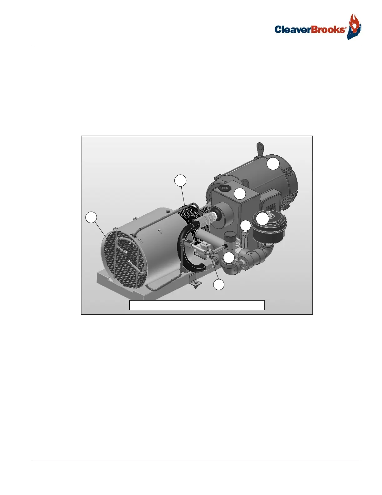
1.2.13 — Air Compressor
A side mounted air compressor provides atomizing air when burning #2 oil. It is started automatically by the
combustion control system. It includes the following components:
1. Air Pump Motor: Drives the air pump and an air cooling fan. The motor is started and stopped simultaneously
with the forced draft fan motor.
2. Air Pump: Provides air for atomization of the fuel oil.
3. Air Filter: The filter cleans the air supply prior to entering air pump.
4. Check Valve: Prevents lubricating oil and compressed air from surging back through the pump and air filter
when the pump stops.
5. Air-Oil Receiver Tank: Holds a supply of oil for lubricating the air pump. The receiver tank also separates lube
oil from the atomizing air before delivery to nozzle.
6. Lube Oil Level Sight Glass: Indicates the level of lubricating oil in the air-oil receiver tank.
7. Lube Oil Cooling Coil: Cools the lubricating oil before it enters the air pump. A fan driven by the air pump
motor circulates cooling air over the coil.
8. Lube Oil Fill Pipe and Strainer: Used when adding oil to the air-oil receiver tank.
FIGURE 1-18. Air compressor
1
2
3
4
5
7
8
6