750-392
CBEX-DE
2-3
Water requirements - hot water boilers
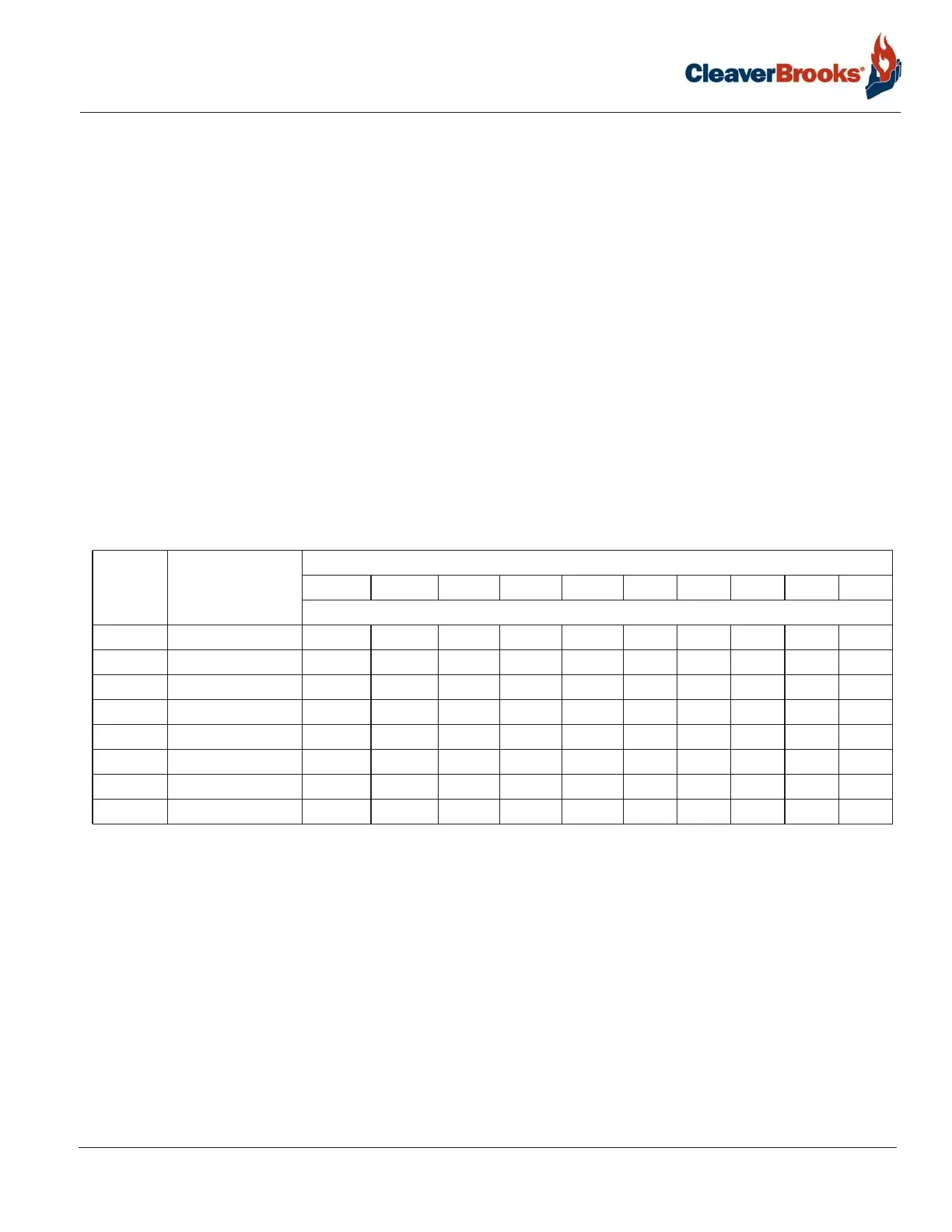
Water Circulation - The chart in Table 2-1 shows the maximum gpm circulation rate of boiler water in relation to
full boiler output and system temperature drop.
It is advisable to have a thermometer installed in the return line to indicate return water temperature. Knowing
the supply water temperature, the boiler system differential can be established. With knowledge of the pumping
rate, the operator can easily detect any excessive load condition and take appropriate corrective action.
Multiple Boiler Installations - When multiple boilers are used, care must be taken to ensure adequate or propor-
tional flow through the boilers. Proportional flow can best be accomplished by use of balancing valves and
gauges in the supply line from each boiler. If balancing valves or orifice plates are used, a significant pressure
drop (e.g., 3-5 psi) must be taken across the balancing device to accomplish the purpose. If care is not taken to
ensure adequate or proportional flow through the boilers, wide variations in firing rates between the boilers can
result. In extreme cases, one boiler may be in the high-fire position while the other boiler or boilers may be at low
fire. The net result would be that the common header water temperature to the system would not be up to the
desired point.
Note: If the operating water temperature going to the system must be lower than 170 deg F, mixing valves
should be used to avoid damage to the equipment. Operating boiler water temperature should be a minimum
of 170 deg F (200 deg F if used to preheat No. 6 oil).
Pump Location - It is recommended that the system circulating pumps take suction from the outlet connection
on the boiler, and that they discharge to the system load. In order to put the boiler and the expansion tank on the
suction side of the pump. The suction side is preferred because it decreases air entry into the system and does
not impose the system head on the boiler. It is common practice to install a standby system circulating pump.
The main circulating pumps are usually located adjacent to the boilers in the boiler room.
Pump Operation - Pumps are normally started and stopped by manual switches. It is also desirable to interlock
the pump with the burner so that the burner cannot operate unless the circulating pump is running.
Pressure - The design of the system and usage requirements often dictate the pressure exerted upon the boiler.
Some systems are pressurized with air, or with an inert gas such as nitrogen. Caution must be exercised to
ensure that the proper relationship of pressure to temperature exists within the boiler so that all of the boiler’s
internal surfaces are fully wetted at all times.
TABLE 2-1. Maximum Circulating Rate
BOILER SIZE
(BHP)
BOILER
OUTPUT
(1000)
BTU/HR
SYSTEM TEMPERATURE DROP - DEGREES °F
10 20 30 40 50 60 70 80 90 100
MAXIMUM CIRCULATING RATE - GPM
250 8,370 1,675 838 558 419 335 280 240 210 186 167
300 10,045 2,010 1,005 670 503 402 335 287 251 223 201
350 11,720 2,350 1,175 784 587 470 392 336 294 261 235
400 13,400 2,680 1,340 895 670 535 447 383 335 298 268
500 16,740 3,350 1,675 1,120 838 670 558 479 419 372 335
600 20,080 4,020 2,010 1,340 1,005 805 670 575 502 448 402
700 23,430 4,690 2,345 1,565 1,175 940 785 670 585 520 470
800 26,780 5,360 2,680 1,785 1,340 1,075 895 765 670 595 535