Preparations for Startup
3-18
750-392
CBEX-DE
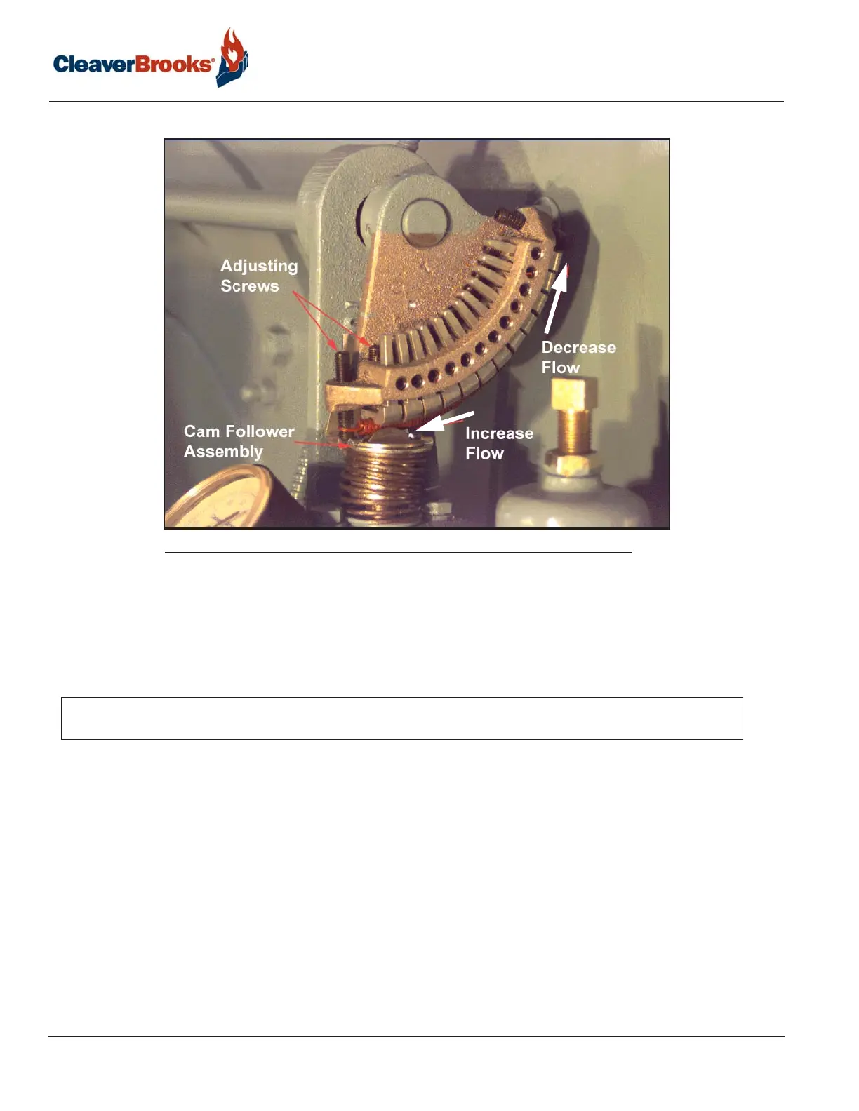
Through the manual flame control switch, position the cam so that the adjusting screw adjacent to the end or
high-fire screw contacts the cam follower. Perform a combustion analysis at this point. If an adjustment is neces-
sary, turn the adjustment screw accordingly to increase or decrease fuel flow. Take a combustion reading to verify
input. Repeat as necessary until the desired flow is obtained. Repeat the process, stopping at each adjusting
screw, until the low-fire adjusting screw is reached.
3.10.2 — Low Fire Adjustment
The fuel input should be adjusted using the low-fire cam screw. At low-fire the O
2
flue gas reading should be
between 6% and 7%.
It may be necessary to readjust the setting of the low-fire stopscrew to obtain the proper air/fuel ratio at the low-
fire rate. To ensure that the low-fire position of the gas butterfly valve is always the same, allow one turn of the
stop screw for overtravel.
If the air damper needs to be adjusted in order to provide the correct low-fire air/fuel ratio, combustion must be
rechecked at higher firing rates and adjusted as required.
If all cam screws are properly adjusted, none will deviate from the general overall contour of the cam face.
NOTE: Do not use any lubricant on the adjusting setscrews. The setscrews have a nylon locking insert
intended to provide locking torque and resistance to loosening.
FIGURE 3-5. Modulating Cam