34 P2077SB/EN 2011-09 77g_Komponenten-en.fm, 06.09.2011
Transducer
8
8.1 Electrical Data
8.2 Pin configuration of transducer
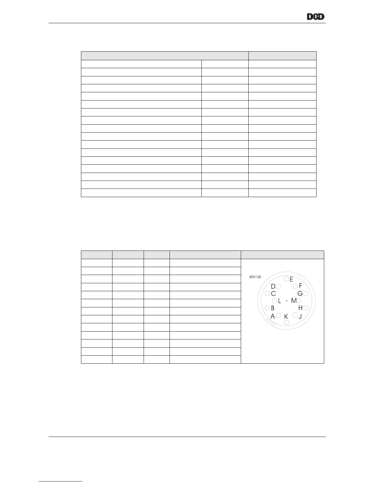
Type: 12-pin circular connector Lumberg SGR 120, Binder series 680 no. 09-0331-90-12
with locking connector in accordance with DIN 45 321
Torque measurement features Data
Nominal supply voltage V +12
Supply voltage limits V +10.75...+12.5
Supply current mA 80
Measured output voltage – nominal voltage V -5…+5
Measured output voltage limits U
N
V ±5.000 ±0.5 % + U
0
Permitted measuring range of rated torque % ±10...±125
Zero voltage limit value U
0
mV ±100
Nonlinearity / Torque measurement % of U
N
±0.25
Measuring accuracy % of U
N
±0.5
Output current, maximum mA 5
Internal resistance Ri, torque output <10
Limit frequency of the torque measurement (-3dB) KHz 2
Measured output voltage calibration ON U
K
VU
N
±0.25%
Calibration voltage, input ON V > 3.5
Calibration voltage, input OFF V < 2.0
Calibration voltage, maximum V 35
Calibration input impedance K 5
Pin Color Signal Description
A–– nc
B Brown – nc
C green TQ Torque output
D Yellow 0 VA 0 V torque reference connection
E gray 0 V 0 V supply
F Pink +12 V Supply
G Blue – nc
H Red RxD+ Interface
Y Black RxD- Interface
K Violet CAL Input calibration voltage
L Gray / pink TxD- Interface
M Red / blue TxD+ Interface
Housing PE Shield connection
 Loading...