70 P2077SB/EN 2011-09 77l_Fehlersuche-en.fm, 06.09.2011
Troubleshooting
15
15.4 Tightening module TSE/TUSE
15.4.1 "Ready" LED
15.5 Nutsetter control unit mPro400GC-M
15.5.1 Display on the Control Unit
All faults and malfunctions that the TSE/TUSE fastening electronics detect are transmitted to the
mPro400GC-M via ARCNET and then displayed on the screen.
If a malfunction develops in the TSE/TUSE or DGD-IS during tightening, the faults reported by the
TSE/TUSE in the rundown data table will appear:
IP, FLT, FMK, FHW, KAL1, KAL2, OFF1, OFF2, VAP, VLP, AN1F, AN2F.
In the bus map window system (see Programming Manual mPro400GC), all current errors are displayed in
plain text in the system information and listed in the following table.
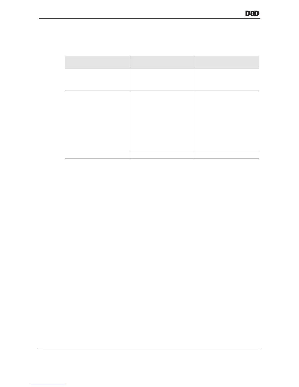
Error
Description
Possible causes Measures and
remedies
"Ready" LED lights up red
Error in the TSE/TUSE For fault description on the
mPro400GC-M display,
see 15.5Nutsetter control unit
mPro400GC-M
"Ready" LED does not light
up
24 V supply is unavailable, the
TSE/TUSE is not connected to
the power supply
➔ Measure the voltage
24 – 26 V at "XS1B",
sockets A and B
➔ Check the error display for
the PDB-CPS… on the
CPS3.
➔ If error present, go to 15.3
Tightening module CPS3 in
power distribution box PDB-
CPS…, page 65
➔ Replace the system cable
TSE/TUSE is defective
➔ Replace the TSE/TUSE

 Loading...