50 P2077SB/EN 2011-09 17i_Kabel en.fm, 25.10.2011
Instructions on laying cables
12
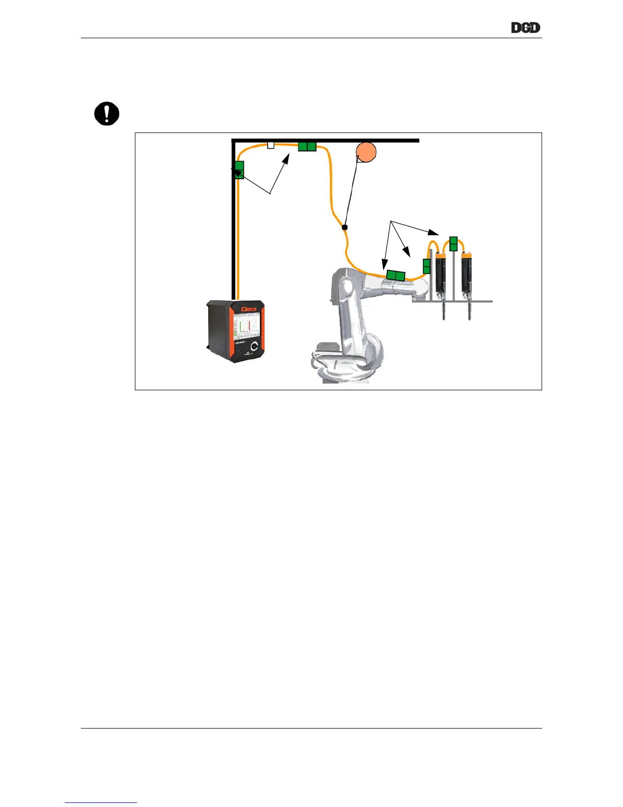
12.2 Strain relief clamp
Fig. 12-1: Use with robot (example, other installations possible)
➔ Position the strain relief clamps so that the cables have maximum freedom of movement. Lay cables in
slight loops such that the cables never become strained when the cable drag chain is pulled out. Cable
pulls between the carriages or end stops on the rail can be of assistance.
We recommend: Run a few motion cycles after the initial installation of cables. Afterwards, check the cable
installation once more and optimize it if possible.
➔ Only secure cables with strain relief clamps designed for the corresponding cable diameter. Use screw-
on cable clips if possible. The clamping surface should be adjusted to the occurring tensile load. Too
narrow of a clamping surface may cause the cable to fail prematurely.
➔ Avoid crushing individual wires or subcomponents.
We recommend applying a clamping force around the entire circumference of the cable.
➔ Only secure the cables at the strain relief clamp.
➔ A secure strain relief clamp prevents the cable from shifting inside the flexible cable duct.
12.3 Shielding
The shielding in the lines limits the expansion of perturbation energy into the surroundings and shields the
system against disturbances.
The cables between tightening module and Built-in nutrunner or hand tool are shielded against exterior dis-
turbances. However, this measure also counteracts interference emissions.
➔ Generally connect it to both ends.
➔ Extensively connect the shielding of the nutrunner cables (skin effect) to the lower edge of the tightening
module housing with the aid of shield connecting elements.
NOTE! ➔ Generally all cable and hose components must be provided with traction reliefs at the beginning and
end of the sections so that no tensile stresses can occur at connectors, plugs and rundowns.
Strain relief clamp
Strain relief clamp

 Loading...