®
www.climacoolcorp.com
18
Hydronic Refrigeration
The ClimaCool Modular Chiller - Hydronic Configuration
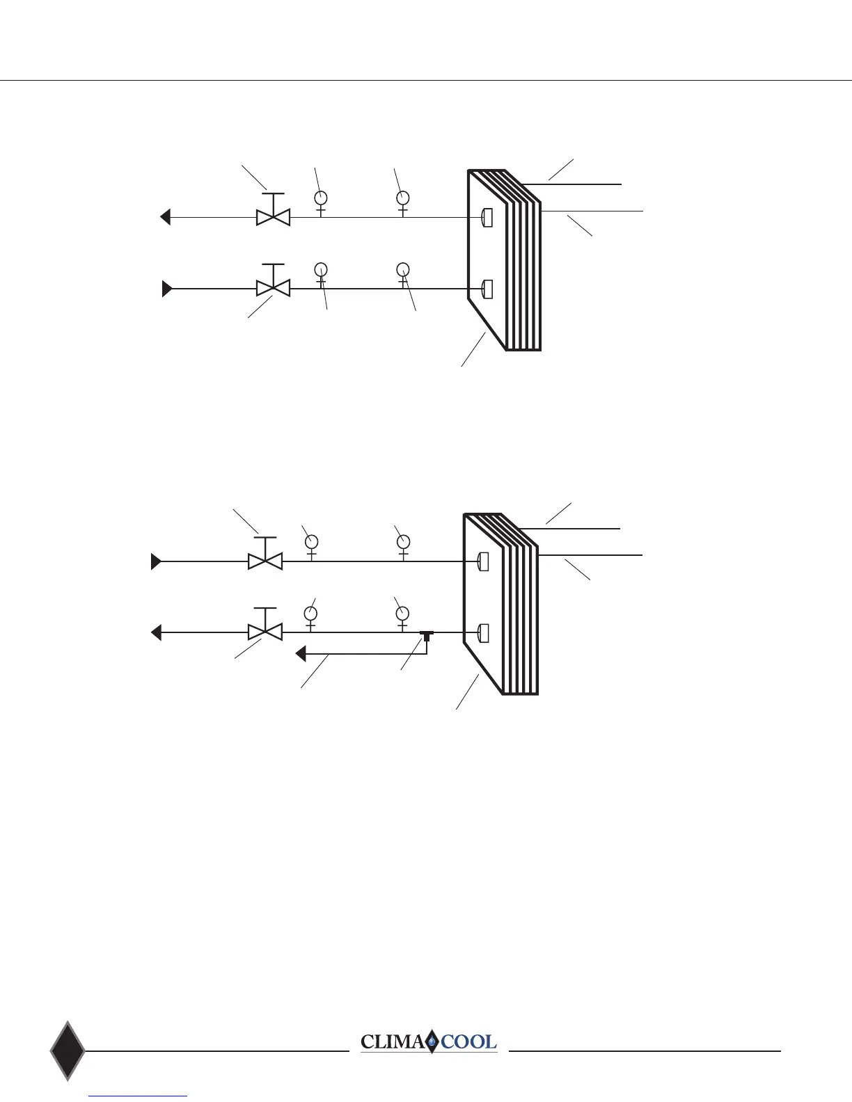
Figure 1 - Condenser Hydronic Circuit
Figure 2 - Chilled Water Circuit
NOTE: Figures 1 and 2 depict hydronic piping in each ClimaCool chiller module.
Heat Exchanger
Refrigerant Circuit #1
Refrigerant Circuit #2
Service Port (3/4”)Pete’s Port
Pete’s Port
Service Port (3/4”)
From Cooling Tower
To Cooling Tower
Header
Header
Isolation Ball Valve (2, 2-1/2 or 3”)
Isolation Ball Valve (2, 2-1/2 or 3”)
Heat Exchanger
Refrigerant Circuit #1
Refrigerant Circuit #2
Service Port (3/4”)Pete’s Port
Service Port (3/4”)
Chilled Water Outlet
Chilled Water Inlet
Sensor Well (internal)
Cap Tube to Low Limit
Protection Thermostat
Header
Header
Isolation Ball Valve (2, 2-1/2 or 3”)
Isolation Ball Valve (2, 2-1/2 or 3”)
Pete’s Port
The ClimaCool Modular Chiller - Hydronic Configuration
Figure 1 - Condenser Hydronic Circuit
Figure 2 - Chilled Water Circuit
NOTE: Figures 1 and 2 depict hydronic piping in each ClimaCool chiller module.
Heat Exchanger
Refrigerant Circuit #1
Refrigerant Circuit #2
Service Port (3/4”)Pete’s Port
Pete’s Port
Service Port (3/4”)
From Cooling Tower
To Cooling Tower
Header
Header
Isolation Ball Valve (2, 2-1/2 or 3”)
Isolation Ball Valve (2, 2-1/2 or 3”)
Heat Exchanger
Refrigerant Circuit #1
Refrigerant Circuit #2
Service Port (3/4”)Pete’s Port
Service Port (3/4”)
Chilled Water Outlet
Chilled Water Inlet
Sensor Well (internal)
Cap Tube to Low Limit
Protection Thermostat
Header
Header
Isolation Ball Valve (2, 2-1/2 or 3”)
Isolation Ball Valve (2, 2-1/2 or 3”)
Pete’s Port
Note: Figure 21 and 22 depict hydronic piping in each ClimaCool chiller module and are shown with water isolation valves.
Figure 21- Condenser Hydronic Circuit
Figure 22 - Chilled Water Circuit